- What are gears
- Types of gears
- Gear design
- Main settings
- Circle diameters
- Gear modules
- Calculation of parameters
- Application
- Gear and gear - differences
- Features of gears and gears
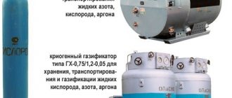
Gear drives are very widely and productively used in the designs of modern machines, mechanisms and devices. Vehicles, power plants, lifting devices, aircraft installations, agricultural machines, precision instruments - all of them contain one or another version of the gear wheel. In technology, gears are used to distribute rotational motion between the axes of shafts, which can be parallel, crossed or intersecting. Also, with the help of such a transmission, it is easy to convert rotational motion, for example, into translational motion, or to realize effective conversion of torque and shaft speeds. Thanks to the latter property, they are used in various types of gearboxes or multipliers, as well as gearboxes.
The main advantages of this method of power transmission are high efficiency; compact design; smooth operation; accuracy; durability; reliability; the ability to transmit force using any angle, gear ratio (up to several thousand) and a wide range of speeds (up to 150 m/s). These qualities determined the spread of the use of gears in technology. Negative aspects include the technological complexity of production; demands on precision processing, materials and processing equipment. The choice of material for a gear is one of the most important criteria for reliability and durability in its further operation. The rigidity of the structure, which ensures high efficiency of the transmission, unfortunately, does not allow it to withstand high values of dynamic loads, which often cause destruction of the mechanism. In addition, these transmissions are characterized by increased noise, which can be reduced by increasing the quality and precision in the production of products.
What are gears
In general, a gear, or cogwheel, is the main part of the transmission of the same name, and has the form of a disk with teeth located on a cylindrical or conical surface. With the help of these teeth, during the rotation process, the wheels engage with each other, which makes it possible to transfer torque from one shaft on which the wheel is located to another. When a tooth of a gear wheel rotates, it pushes the tooth of another wheel connected to it, which, as a result, also begins to perform a rotational movement.
The mating gear train must always consist of two types of elements: driving and driven. In this case, the driving wheel, by definition, is the wheel that transmits (communicating) rotation, the driven wheel is the gear that has a large diameter with a large number of teeth and causes rotation. In most cases, a pair of gears is used, one with a large number of teeth and the other with a smaller number. Sometimes the element that has fewer teeth is considered a gear, while the one with more teeth is considered a wheel.
Driven spur gear - Great Encyclopedia of Oil and Gas, article, page 1
Driven spur gear
Page 1
The driven spur gear is 15 helical. The gear is made of steel 25ХГНМ, is carburized to a depth of 1 2 - 1 6 mm and hardened to ensure a hardness of 60 - 64 HRC. The gear assembly with the differential on two bevel bearings is installed in the gearbox housing. The gear is installed on the differential cups on a sliding landing and is attached to them with bolts 59 with self-locking nuts. [1]
The crown of the driven spur gear 24 is installed between the two flanges of the cups 7 of the differential box. The cup flanges and the gear ring are connected with rivets. The differential box rotates in ball bearings 22, which are kept from moving by retaining rings. [2]
The driven spur gear bearings should be adjusted preloaded. [4]
The crown of the driven spur gear must be positioned symmetrically relative to the crown of the drive gear. [5]
Next, from the driven spur gear through the differential and axle shafts 11, torque is transmitted to the drive wheels. [7]
For the forging (weighing 30 kg) of the driven cylindrical gear of the main transmission of the ZIL-130 vehicle, cooling is used in a tank of water, where the forging enters directly after the cutting die. After 18 s, the forging is transferred by a conveyor belt from the tank to the container. [8]
The drive bevel gear shaft meshes with a driven spur gear, which is riveted to the cups of an automotive-type differential box. [9]
The differential consists of the right and left cups, a driven spur gear, a spider, four satellites and two side gears. [10]
The crosspiece is mounted in the differential cups and rotates with them and the driven spur gear. [12]
Ichernya; 11 Н 13 — nuts for adjusting the intermediate shaft bearings; 72 — driven cylindrical gear. [13]
The restored differential box cup must meet the following basic technical requirements: when installed on the surface under the hole of the driven spur gear and supported on the end of the contact with the driven spur gear, the runout of the spherical surface is no more than 0 06 mm; radial runout of the surface of the journal for the bearing and the hole for the journal of the axle gear is no more than 0 08 mm; end runout of the surface under the axle gear washer is no more than 0 05 mm; surface roughness of the bearing journal no more than Ra 1 25 microns; The difference in size b for one part is no more than 0 08 mm. [15]
Pages: 1 2 3
www.ngpedia.ru
Types of gears
All gears, the types of which are as numerous as the options for their application, are divided into main types according to the location of the shaft axes and the geometry of the teeth. There are cylindrical, bevel, worm, and screw gears. In practice, based on the shape of the tooth profile, involute and circular gears are distinguished, and according to their location, spur and helical types of gears are distinguished.
For the parallel case of shaft axes, cylindrical gears are used:
- straight teeth;
- with circular teeth;
- chevron;
- helical.
Bevel gears are suitable for intersecting axes:
- with curved teeth;
- helical;
- with zero tilt angle;
- straight teeth.
When the axes intersect, then gears are used:
- spiroid;
- hypoid;
- screw;
- worm-type
Cylindrical gears have become the most widespread among machines and mechanisms. They are characterized by ease of manufacture, reliability, and small dimensions. Bevel, worm and helical types of gears are used only when the layout of the machine imposes special conditions. Cylindrical gears are divided into two essential types: external and internal gearing. In the first embodiment, the externally geared wheel and gear rotate in directions that are opposite to each other. In the second, the internal gear wheel and the external gear perform rotational movement in a directional direction. There is also a rack and pinion transmission - in it, a rack with teeth mates with an externally meshed gear.
Helical cylindrical wheels have teeth located at an angle to the axis. The mating wheels have the same tooth inclination, but different directions. One will tilt to the right, while the other will tilt to the left. The presence of an inclination makes it possible to transmit larger loads compared to straight teeth, promotes smooth engagement of the teeth and reduces noise.
Chevron wheels are a pair of connected wheels with oblique teeth that have an equal angle of inclination, but are located oppositely: one with a right inclination, the second with a left inclination. This allows the axial forces to be balanced, thereby reducing the load on the bearing. Wheels may have a groove in the middle. Wheels without a groove are more durable, but difficult to manufacture.
Helical cylindrical gears, in turn, are used to rotate shafts when their crossing angle lies in the range from 0 to 90 degrees. They are similar to helical gears, but the helical gear has a point contact rather than a linear contact like a helical gear. The direction of inclination of the teeth of all such mating wheels is the same. Point contact of teeth causes increased wear, and as a result they are used only under light loads.
Rack and pinion gears are made up of gears and racks, which also have teeth. Rotating, the cylindrical wheel moves the mating rack along a straight line perpendicular to the axis of the wheel. In this way, the movement turns from rotational to translational. This type of transmission can be used with both oblique and straight teeth.
Straight bevel gears have teeth that intersect the axes of these wheels. The conical arrangement allows rotation of intersecting or crossing axes. The teeth can also be oblique, i.e. tangent to the circle. The angle of inclination of the teeth of such wheels is no more than thirty degrees. Supplying bevel wheels with teeth with a zero angle of inclination provides the first with low axial and radial loads and makes it possible to use plain bearings. These qualities make transmissions using such wheels compact and inexpensive to manufacture.
The use of curved teeth for bevel gear applications dramatically reduces gear noise and increases strength. Bevel gears of this kind always have at least two teeth in mesh, which gives them the ability to withstand a load that is 30% higher than identical spur gears and wheels with zero inclination.
Hypoid gears are similar to bevel gears, but the axis of the drive gear is offset higher or lower relative to the axis of the wheel it drives. In such gears, the gears have a greater tooth angle than the wheels. In this case, the normal pitch of the pinion and gear will be the same, but the face pitch will be larger for the gear. The hypoid transmission is not characterized by pure rolling or sliding; all its points are subject to sliding. This gives it smoothness and increased noiselessness. In addition, grinding in occurs faster and with better quality. The downside is that the presence of sliding causes increased wear on the surface of the teeth, which requires the use of specialized oils for such gears.
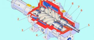
Cylindrical worm gears have a worm having the geometry of a cylinder, on which turns are cut, running along the direction of the helix. The worm wheel must have concave teeth. The linear contact of such teeth ensures the transmission of large loads. The slip of worm gears is much higher than that of other gears. In a globoid gear, the worm has a concave shape. This feature allows a larger number of teeth to participate in the engagement process, which increases the magnitude of the loads transmitted by such transmission.
Spiroid gears occupy an intermediate place between worm and hypoid variants. Unlike a worm gear, in a hypoid gear the worm is cone-shaped and engages with a wheel on which the teeth are located on the end side.
Tooth shape
Gears vary in tooth profile and type . Based on the shape of the tooth, involute, circular and cycloidal gears are distinguished. The most commonly used are involute gears. They have technological superiority. Cutting teeth can be done with a simple rack and pinion tool. These gearings are characterized by a constant gear ratio, independent of the displacement of the center-to-center distance. But at high powers, disadvantages appear due to the small contact patch in the two convex surfaces of the teeth. This can lead to surface damage and chipping of surface material.
In circular gearing, the convex teeth of the gear mesh with the concave wheels and the contact patch increases significantly. The disadvantage of these gears is that friction appears in the wheel pairs. Types of gears:
- Straight teeth. This is the most commonly used type of wheelset. Their contact line is parallel to the shaft axis. Spur gears are relatively cheap, but their maximum transmitted torque is less than that of helical and chevron wheels.
- Helical teeth. Recommended for use at high speeds, they provide smoother running and reduced noise. The disadvantage is the increased load on the bearings due to the occurrence of axial forces.
- Chevron. They have the advantages of helical wheel pairs and do not load the bearings with axial forces, since the forces are directed in different directions.
- Curvilinear. Used for large gear ratios. Less noisy and better at bending.
Straight-toothed wheel pairs are the most common. They are easy to design, manufacture and operate .
Gear design
Metal gears, the design of which is sometimes quite complex, have a variety of designs, but they can be divided into three main components: the ring with teeth, the hub and the wheel itself. The ring gear is the main component and bears the brunt of the load. The teeth have different geometries. The outer part of the tooth is the apex, the side parts adjacent to it are the head of the tooth. The inside of a tooth is called its pedicle. The space between the two nearest legs forms the wheel cavity. To attach a gear or wheel to a shaft, a hub is located in the center of the disk, which has a through hole, the shape of which directly depends on the cross-section of the shaft: it can have the shape of a cylinder, square or any other polygon. In the case of cylindrical shafts, the hub often has a so-called keyway In order to save materials and weight of the wheel, its disk has a thickness that is smaller than the thickness of the rim and hub. Often various holes are also made in the disk for these purposes.
Driven bevel gear - Great Encyclopedia of Oil and Gas, article, page 2
Driven bevel gear
Page 2
The shaft with the driven bevel gear is installed in the crankcase on roller bearings. At the ends of the shaft there are gaskets for adjusting the bearings. With proper engagement, the side clearance at the wide part of the tooth should be 0 15 - 0 4 mm. The driven bevel gear shaft is made together with the 10th drive cylindrical gear. There are three pockets in the final drive housing. When the gears rotate, oil enters them, which flows through the channels to the bearings, and from there again into the crankcase. [17]
In a MAZ-200 car, the driven bevel gear is pressed onto the intermediate shaft using a key, all the way to the end of the drive cylindrical gear. The intermediate shaft in these cars rotates on two tapered roller bearings, the outer bearings of which are installed in the covers. The inner rings of the bearings are pressed onto the shaft journals, and shims are placed under the bearing caps (sockets). [18]
In the GAZ-51 car, the driven bevel gear is riveted to the flange of the left differential cup. [19]
The driven bevel gear shaft bearings are adjusted by reducing the number of spacers installed under the flange of the left bearing seat. The standard kit includes gaskets with a thickness of 0 1; 0 15; 0 2 and 0 5 mm, set as required. The axial clearance in the bearings is determined by an indicator during axial movement of the gear. [20]
The heads of the rivets securing the driven bevel gear must have a geometrically correct shape without distortions, sagging or cracks. The spur gear shaft bearings must be adjusted with preload. [21]
Accordingly, the position of the driven bevel gear bearings and a number of parts installed on the rear axle has been changed. [23]
When installing it in the crankcase of a ZIL-150 car, the outer rings of the roller bearings of the driven bevel gear are installed in the gearbox cover until it stops. Roller bearings are lubricated with grease and adjusted with preload - according to the force required to turn the gear. One gasket with a thickness of 0 05 - 0 10 mm is installed under each gearbox housing cover, the rest - as needed. [24]
When adjusting the gear engagement, the driven bevel gear is moved relative to the drive by rearranging spacers 2 and 5, and the drive relative to the driven by changing the number of spacers 5 under the bearing housing of the drive bevel gear shaft. The lateral clearance between the teeth of the bevel pair of the new main gear should be 0 24 - 0 48 mm. [25]
When adjusting the gear engagement, the driven bevel gear is moved relative to the driving one by rearranging spacers 2 and 5, and the driving one is moved relative to the driven one by changing the number of spacers 8 under the bearing housing of the driving bevel gear shaft. The lateral clearance between the teeth of the bevel pair of the new main gear should be equal to 0 24 - 0 48 mm. [26]
On the same shaft with the driven bevel gear 12 of the reverse mechanism, a cylindrical timing gear 14 is fixed, which is in constant mesh with gears 15 and 16, freely sitting on their shafts. [27]
The preload value of the bevel gear bevel bearings should be in the range of 0 03 - 0 05 mm. Bearings are adjusted by changing the gaskets under the bearing caps (sockets). [28]
Before assembling the gears, the driven bevel gear should be heated to a temperature of 120 - 160 C and assembled while hot. [29]
The differential box / is driven through the driven bevel gear 2 of the main gear. [thirty]
Pages: 1 2 3 4
www.ngpedia.ru
Main settings
To ensure the possibility of designing efficient gears, the dimensions of wheels and gears, as well as their strength and weight and size characteristics, are described by special parameters, the values of which are well standardized by GOST. Thus, the involute profile, which is the basis for the tooth section of the vast majority of wheels, is characterized by the engagement module and the number of teeth on the wheel or gear. Quite often, involute gears, having the same diameter, can have significantly different values of these quantities. The circumferential module, which serves as the main characteristic for teeth, according to the standard can have values in the range from 0.05 to 100 mm. The main parameters of the geometry of various gears are the following diameters: initial, main and pitch. The pitch of a gear is the total distance between the width of the tooth and the root. Another important parameter is the radius of the wheel. The radii of gear wheels are divided into: radius of the vertex circle, radius of the pitch circle, radius of the main circle, radius of the valley circle.
Driven gear - final drive
Driven gear - final drive
Page 2
K-701: / — differential housing cup; 2 and 4 - driven coupling halves; 3 - key; 5 and 13 — springs; 6, 7 and 12 - hubs; 8, 9 and / / - rings of the driven coupling half; Yu - drive coupling; b - cam of the GAZ-66 car: / - separator; 2 - crackers; 3 — outer sprocket connected to the right axle shaft; 4 — internal sprocket connected to the left axle shaft; 5 — driven gear of the main gear. [17]
PTO; 29-hollow synchronous PTO drive shaft; 30-drive clutch shaft gear; 32, 51 — reverse driven gears; 33 — reverse gear; 34 — reverse gear and slow gear; 35 — reverse gear shaft; 36 — slow gear; 37 — intermediate gear; 38 — differential lock gear clutch; 39-axle shaft; 40, 49, 52 bearing housings; 47-differential cover; 42-pin; 43-axis satellite; 44 — thrust plate and shims; 45 — satellite; 46 — driven gear of the main gear; 47 — differential housing; 48 — semi-axial gear; 50 — gear clutch for reverse switching; 54 - tubular shaft; 55-reverse shift lever; 56 — reverse fork lever; 57-cover; 55-rod differential lock mechanism; 59 — rod guide; 60 - spring. [19]
Hardening of gears in presses. In tractor mechanical engineering, there is a group of gear wheels of complex configuration (driven gears of main gears, rear axles and final drives of tractors and self-propelled chassis and some gearbox gears), hardening of which, in order to increase manufacturing accuracy, must be carried out in a fixed state in the dies of special presses. [20]
Pressure disk 8 is connected to the shutdown mechanism, the lever of which goes into the tractor cabin. If the levers are in a free state, which corresponds to the engaged turning clutches, the force from the driven gear of the main drive is transmitted to both clutches, and the tractor moves in a straight line. [22]
The satellites are in constant mesh with the gears of the right and left axle shafts. When the car moves on a straight and level road, both driving wheels (right and left) encounter equal rolling resistance, while the driven gear of the final drive rotates the differential box with the spider and satellites. [23]
To ensure correct installation of the gear meshing, the main gear designs provide adjustment devices for the mutual movement of the gears in the axial direction. In most tractors, the correct position of the gearbox drive gear is checked with a template or ruler according to the distance A (Fig. 113) from the end of the small cone of the gear to the mating plane of the gearbox housing, and when installing the gearbox on the tractor, the distance B from the end of the drive gear to the tractor is also checked with a template. axis of the driven gear of the main gear. Shaft 3 with centering disks / is placed in the side holes of the transmission housing, and caliber 2 should touch the end of the drive gear, thereby ensuring the required dimension B (Fig. 113), equal to 133 3 mm for the DT-75M tractor. [25]
In the box on the crosspiece, the satellite gears 5 rotate freely, meshed with the semi-axial gears 6 of the left and right wheels. The axle shafts 77 pass freely through the holes in the differential box. When the driven gear of the main gear rotates, the differential box and spider with satellites rotate along with it. [26]
The input shaft 17 (Fig. 61) is made in the form of a block of drive gears, which are in constant engagement with the driven gears of all forward gears. The main gear drive gear is made together with the secondary shaft. The main drive driven gear is attached to the differential box flange. [27]
The main gear drive gear is made together with the secondary shaft. The final drive differential is two-satellite. The main drive driven gear is attached to the differential box flange. [29]
Pages: 1 2 3
www.ngpedia.ru
Circle diameters
A gear wheel is described by several circles, which are important characteristics of their geometry. Thus, the diameter of the vertices gives the maximum dimensions of the gear. The diameter of the circle of the depressions is opposite to it. By calculating the difference between these two values and dividing it in half, we get the total length of the tooth. An important parameter is the diameter of the pitch circle, which has the formula d=pz/3.14; from it you can determine the circumferential pitch p of the teeth located on the wheel, otherwise called the pitch of engagement, which has a geometric meaning of the part of the length of this circle per tooth. In general, the diameter of the pitch circle separates the height of the heads and the height of the legs of the teeth. It also sets the curve, which is the necessary basis for constructing the involute itself, and is used to construct the profile of wheel and gear teeth required for a specific task.
Gear production technologies
Run-in method. The production of gears in this way is possible using a comb - a tool in the form of a gear rack with a sharpened cutting edge. The comb makes translational or reciprocating movements relative to the workpiece rotating around its axis.
The running-in method is also possible using a cutter shaped like a cutting gear. Since the thickness of the metal does not allow such a process to be carried out in one stage, the cutter makes reciprocating movements relative to the workpiece several times. The method is applicable in the production of internal gears.
It is possible to run in using a hob cutter as a cutting tool, by forming a worm gear with the gear blank. Gear teeth are cut by rotating the hob cutter and the workpiece at a certain angle relative to each other.
The main advantage of the rolling method is the ability to make gears with different tooth shapes with the same tool, changing its position relative to the workpiece on the machine. This technology is more accurate than copying.
Copying (dividing) method. This type of gear production involves cutting the cavities of the gear wheel with a cutting disk or finger cutter, alternately rotating by one angular step. A variation of the technique is stamping and broaching.
Hot and cold rolling. The method is based on thermal layer-by-layer heating of the workpiece and its deformation to cut teeth, followed by rolling to give the shape precision.
Manufacturing of bevel gears. This is the rolling of a workpiece in machine engagement with an imaginary production wheel. As the tool moves, it cuts off the allowance, forming the side surfaces of the gear.
Production of shaft and gears. This assembly mechanism consists of the shaft itself and a gear, the size of the teeth of which is equal to the size of the cavities of the shaft. It is done assembled.
Gear modules
To simplify the calculations of the elements used for gearing, a standardized GOST value called the module was introduced for gears. The gear module is the part of the diameter of the existing gear pitch circle that falls on the tooth: m=d/z. Thus, the number of teeth of a wheel, its own pitch diameter and its module are mutually influential. The module can be written as the ratio of the wheel engagement pitch and the Pi number: m=d/3.14. When the load transmitted by gears is small, it is better to use small modules. The small module gives longer service life and simplifies gear processing. In this case, there will be more teeth on the pitch diameter, which means that engagement will occur with a larger number of them, which will reduce the load on individual gear teeth. Spur gears have only one module, helical gears have two: normal and circumferential. The first one is used in calculations.
Product specifics
Due to its operational characteristics, the gear shaft belongs to the group of units that are often subject to serious and rapid wear. This is due to the nature of the mechanism’s operation - during the transmission of torque, the gear shaft itself is influenced by various forces and experiences a load on the structure. Similar adverse effects come from both supports and parts that engage the shaft. Gear shafts that have a conical shape are particularly susceptible to wear - they are simultaneously affected by concentrated radial and axial loads, and the transmission of rotational torque itself contributes to the consistent deformation of the elements of the part and the physical wear of the unit. Failure to timely replace a worn gear shaft can lead to its complete failure and suspension of equipment operation.
Calculation of parameters
For all gears, the engineering calculation of their parameters is a complex task, during the solution of which the design of the entire transmission is taken into account. First you need to decide on the number of teeth and the gearing module required for the task. To select the latter, the parameters of strength and expected service life of the wheels are required; the material from which it will be made. Based on these data, the minimum possible value of the engagement modulus in a given problem is calculated, which is then reduced to standardized values found from the corresponding tables. The gear ratio is calculated using the formula u=z2z1, where z2 is the number of wheel teeth, and z1 is the number of teeth on the gear. It allows you to understand how many teeth are needed on the wheels to be mated. Knowing the modules and the resulting number of teeth for all wheels and gears, further calculations of the dimensions of the required parts can be made using a standard method for their calculations.
Maintenance and billing
Maintenance consists of inspecting the mechanism, checking the integrity of the teeth and the absence of chips. Checking the correct engagement is done by applying paint to the teeth. The size of the contact patch and its location along the height of the tooth are studied. Adjustment is made by installing spacers in the bearing units.
First you need to decide on the kinematic and power characteristics necessary for the operation of the mechanism. The type of transmission, permissible loads and dimensions are selected, then materials and heat treatment are selected. The calculation includes the selection of the engagement module, after which the displacement values, the number of gear and wheel teeth, the center distance, and the width of the rims are selected. All values can be selected from tables or using special computer programs.
The main conditions necessary for long-term operation of gears are the wear resistance of the contact surfaces of the teeth and their bending strength.
Achieving good performance is the main focus in the design and manufacture of gear mechanisms.
Application
Each type of transmission has its own advantages and disadvantages. Cutting spur gears is a fairly simple technological process, which is why they are widely used in industry. Helical and spur gears are used in tractors, machine tools, and vehicle gearboxes. Due to their compactness and strength, cylindrical wheels using internal gearing have found themselves in aircraft, automobile transmissions, gearboxes, splined joints and complex planetary gears, which are famous for their particularly low weight and overall dimensions. At the same time, they provide high gear ratios and significantly reduced noise levels during operation. Chevron wheels, being labor-intensive to manufacture, are used in large gearboxes and their repair, where smooth and silent transmission of significant loads is required. Bevel wheels with zero inclination and their straight-toothed analogues, having high compactness and low manufacturing costs, are used in differentials of cars and machine tools. Curved teeth provide bevel wheels with special strength and low noise, so they can be found in critical and high-speed gears. They are used almost everywhere: from airplanes to tractors. Hypoid gear pairs can be made with high gear ratios (up to 100:1) and are often used in metal-cutting equipment.
Materials for production
The main material for making wheelsets is steel. The gear must have higher strength characteristics, so wheels are often made of different materials and subjected to different thermal or chemical-thermal treatments. Gears made of alloy steel are subjected to surface hardening by nitriding, carburizing or cyanidation. For carbon steels, surface hardening is used.
The teeth must have high surface strength, as well as a softer and more viscous core. This will protect them from breakage and surface wear. Wheel sets of low-speed vehicles can be made of cast iron. Bronze, brass and various plastics are also used in various industries.
Gear and gear - differences
The main parts in a gear drive are the gear and pinion. They are used in many industrial units and machines. Many people believe that a gear and a gear are the same part and there are no differences between them. Specialists who are closely associated with industry and mechanical engineering do not think so and I assure you that these are different parts, although they essentially perform the same function of transmitting rotational motion. Let's look at the main points on this issue.
Let's summarize
Design drawings and diagrams for gears of various configurations are mainly the same for oblique and spur versions. The main differences arise in strength calculations. Graphic displays use characteristics based on typical overall dimensions of gears. Among the assortment presented on the market, it is quite possible to select a gear with the necessary characteristics and strength indicators.
Sources
- https://mehmanxona.ru/tehnologii/vidy-shesterenok.html
- https://novoe-info.ru/chto-takoe-modul-shesterni/
- https://MechPrivod.com/market/zubchataya_shesterenka/shesterenka_zubchataya_cilindricheskaya/
- https://novoe-info.ru/kak-nayti-modul-zubchatogo-kolesa/
- https://doctordent.su/pulpit/kak-opredelit-modul-zuba-shesterni-po-diametru.html
- https://FB.ru/article/429020/modul-shesterni-vidyi-opredelenie-standartnyie-pokazateli
Features of gears and gears
Externally, a gear wheel and a gear are similar in the form of a disk with teeth located on it. Their location can be either on a conical or cylindrical surface. The main task of these parts is to transmit torque. In order to receive and transmit torque, you need a counter gear, that is, a pair. We discussed above that there is a driven part and a leading one. Movement begins from the driving part and further transmission of torque to the driven part begins. This key point is the difference between a gear and a gear; the driving part is a gear, and the driven part is a gear. It turns out that the whole difference between them is what role the part plays in the mechanism.
Note that when two gears operate, the wheel that has the greater number of teeth is called a gear. In GOST 16530-83 there is an explanation that gear and gear are synonymous words, gear is the main and driving gear. There are specialists working in certain areas of industry and mechanical engineering who clearly distinguish the difference between a gear and a gear. They are convinced that making gears is one thing and making gears is another because there are differences between them.
Hyperboloid gears with initial linear tangency
Worm gears with a cylindrical worm (Fig. 12) are used to connect shafts whose axes usually intersect at right angles. The worm is a helical gear with a large angle of inclination of the teeth (worm turns). Due to the linear contact between the worm gear teeth and the worm threads, the worm gear can transmit significant loads at high speeds. High sliding speeds in meshing force us to pay special attention to the selection of materials for the worm and worm wheel and the selection of lubricants that prevent jamming.
The globoid worm gear (Fig. 13) is a further development of the worm gear. The concave shape of the worm ensures that a larger number of teeth are engaged in engagement than with a cylindrical worm. Due to the high thermal stress, the globoid worm gear is used, as a rule, in mechanisms with intermittent operation. The load-bearing capacity of a globoid worm gear, all other things being equal, is significantly higher than that of a worm gear with a cylindrical worm.