Electric arc welding requires electricity of certain parameters: high power (amperage), low voltage (voltage). Under the influence of current, a powerful electric discharge is formed between the end of the electrode and the metal being welded, and a large amount of heat is released. Various converters are used as power sources for the welding arc. Over the history of manual electric welding, devices have been created to ignite the arc that generate alternating and direct current. First there were transformers, after the advent of semiconductors, rectifiers were created. Generators convert energy from burning liquid or dry fuel into electric current. Inverters are new generation sources; their arc power capabilities are much wider than those of transformers. When choosing a welding machine, it is advisable to take into account the advantages and disadvantages of the devices.
Brief historical background on the development of power sources for arc welding.
| Welding power source type | Since what year has it been used (approximately) |
| Welding converter (electric motor + generator) | ≈ 1905 |
Transformer | ≈ 1920 |
| ≈ 1950 |
Welding thyristor rectifier | ≈ 1970 |
Welding inverter | ≈ 1980 |
Arc welding power supplies provide electrical energy to the welding process. At the same time, they have a significant impact on the nature of the welding process (primarily on quality and productivity). Therefore, a deeper understanding of the properties of power sources and the principles of their operation is mandatory for those who intend to work in the field of welding (although, of course, the following brief classification of power sources and a somewhat simplified discussion of their properties does not imply complete information on this issue).
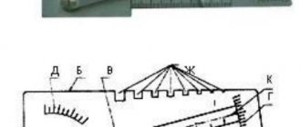
2.1.2. Current-voltage characteristic of the arc (volt-ampere)
The most important characteristic of the arc is the dependence of the voltage on it on the current value. This characteristic is called current-voltage. There is a static current-voltage characteristic and a dynamic current-voltage characteristic.
the arc temperature increases, thermal ionization increases, the number of ionized particles in the discharge increases and the electrical resistance of the arc decreases .
The arc voltage is equal to
.
The dependence of the voltage on the arc on the current when it changes slowly is called the static current-voltage characteristic of the arc.
The static characteristics of the arc depend on the distance between the electrodes (arc length), the material of the electrodes and the parameters of the environment in which the arc burns.
a) Static current-voltage characteristic
, —
arc voltage;
—
sum of near-electrode voltage drops;
—
field strength in the arc column;
depends on the current and the conditions under which the arc burns. The static current-voltage characteristics of the arc are as follows:
The longer the arc length, the higher its static current-voltage characteristic lies. As the pressure of the medium in which the arc burns increases, the intensity E
and the current-voltage characteristic rises. Arc cooling significantly affects this characteristic. The more intense the cooling of the arc, the more power is removed from it. In this case, the power released by the arc should increase. For a given current, this is possible by increasing the arc voltage. Thus, with increasing cooling, the current-voltage characteristic rises. This is widely used in arc extinguishing devices of apparatus.
The arc current-voltage characteristic (Fig. 1) is shown for low current densities (up to 100 A/mm 2 ). With a further increase in current, the current-voltage characteristic becomes horizontal. If you continue to increase the current, the voltage will begin to increase.
Brief classification of power sources for arc welding
As shown in the diagram below, arc welding power sources can be classified according to various criteria.
According to the first criterion, power supplies are classified according to the method of energy production: whether it is converted from the power supply network (as is the case with transformers, rectifiers and electronic power supplies) or generated by the power supplies themselves (as is the case with generators).
According to the second criterion, power sources are classified according to the method of converting electrical energy:
- by using transformers that convert the relatively high voltage of the power network into a lower voltage for welding with alternating current; — by using welding rectifiers, consisting of a transformer (to reduce the voltage of the power network) and a rectification unit to convert alternating current into direct current; — by using electronic power sources (for example, welding inverters); - by using welding converters consisting of a welding generator, the rotation of the rotor of which is provided by an electric motor; — by using welding units consisting of a welding generator, the rotation of the rotor of which is ensured by an internal combustion engine (strictly speaking, the unit converts not electrical energy, but mechanical into electrical energy).
The third classification feature is the method of obtaining energy: power sources can be dependent (all except units, since they receive energy from a stationary electrical network) and autonomous (units, since their generator is connected to an internal combustion engine).
According to the fourth criterion, power sources are classified in accordance with the method of regulating welding parameters. In transformers and rectifiers, this can be done using moving coils, moving magnetic shunts, sectioning the turns of the secondary winding and other methods.
The fifth classification feature is the type of welding current that is provided by power sources: alternating (AC), direct (DC) or both, both AC and DC (combined power sources).
According to the sixth classification criterion, power supplies are classified in accordance with the form of the external (static) current-voltage characteristic (V-VAC). The external current-voltage characteristic of the power source is the dependence of the average voltage at the source terminals on the current strength in the welding circuit. It can be either falling (CC - constant current) or hard (CV - constant voltage). In both cases, these definitions are not entirely accurate and are conditional, accepted in welding practice. For more information about the current-voltage characteristic, see Volt-ampere characteristic of the arc
Uхх – open circuit voltage
Power supplies with a falling I-V characteristic are characterized by the following basic properties:
— have a high open-circuit voltage (≈ 2 ... 2.5 times higher than the operating arc voltage); — the voltage at the power source terminals drops significantly as the welding current increases; — have a limited short-circuit current (not higher than 1.1 ... 1.3 of the rated welding current).
Power supplies with rigid V-voltage characteristics are characterized by the following basic properties:
— the no-load voltage is only slightly higher than the operating arc voltage; — the voltage at the power source terminals drops slightly as the welding current increases; - short circuit current can reach very high values (2 ... 3 times higher than the rated welding current).
The shape of the external current-voltage characteristic of the power source is determined experimentally by measuring the voltage at the external terminals of the power source (Un) and the current in the circuit (I) with a smooth or stepwise change in the load resistance (Rн) and at constant values of the open circuit voltage, active and inductive components of the internal resistance power supply. As the load resistance decreases, the current in the circuit increases, the voltage drop inside the power source increases and, accordingly, the voltage at the external terminals of the power source (Un) decreases. The rate of voltage decrease Un (in other words, the slope of the external current-voltage characteristic) is determined by the value of the internal resistance of the power source. The higher the internal resistance of the power supply, the steeper the external current-voltage characteristic of the power supply becomes.
The static I-V characteristic should not be confused with the dynamic characteristic of the power source, which characterizes the rate of change of instantaneous current values in the welding circuit.
The table below presents data for selecting the type of current and the shape of the I-V characteristics of the power source, depending on the arc welding method.
| Welding method | D.C | Alternating current | |
| Falling | Tough | Falling | |
| Manual arc welding (MMA) | Yes | No | Yes |
| Tungsten inert gas arc welding (TIG) | Yes | No | Yes |
| Mechanized arc welding with a consumable electrode in shielding gas (MIG/MAG) | No | Yes | No |
Welding power sources are also designed for different operating modes, which are assessed by the relative operating duration (OL; sometimes designated as LO - Load Period):
PR = (working time (welding) / time of the entire cycle (welding and pauses) = 10 min) * 100%
The duration of the entire work cycle (welding and pause) for sources is assumed to be 10 minutes. For example, if PR = 20%, then this means that after 2 minutes of welding at rated current, it is necessary for the source to cool for at least 8 minutes. Otherwise, it may overheat and fail.
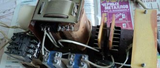
Four types of converters
The main difference between welding arc power sources, which determines their technical characteristics, weight, dimensions and scope of application, is the difference in the principle of electric current conversion.
The following types of sources exist:
- transformers;
- rectifiers;
- converters;
- inverters.
Generators, the so-called units, stand apart. These machines are not secondary, but primary sources of energy; they do not convert power from a city or industrial network in one way or another, but generate it themselves.
As a rule, units are built on the basis of an internal combustion engine - gasoline or diesel. The former are cheaper, the latter have greater power and service life.
Design features of welding transformers
The current of the welding transformer is regulated in various ways. Currently the most used of them are:
When a magnetic shunt is introduced into the magnetic circuit of a transformer, part of the magnetic flux created by the primary winding is removed by the magnetic shunt and therefore this part of the magnetic flux bypasses the secondary winding. In this case, the efficiency of energy transfer from the primary winding to the secondary winding decreases and, as a result, the welding current decreases. In the second method, when the windings are separated, their magnetic coupling deteriorates and the efficiency of energy transfer from the primary winding to the secondary winding decreases. As a result, the welding current is reduced. Both of these methods provide smooth control of the welding current. Moreover, due to the constant number of turns of the windings, the no-load voltage of the transformer remains unchanged. Welding transformers of this type provide incident V-V characteristics and are thus suitable for manual arc welding with covered electrodes.
Technology
The entire technological process of manual arc welding, as in the case of other welding methods, is divided into three main stages:
- preparatory;
- basic;
- final.
Preparatory stage
Due to the fact that manual arc welding is used very often in domestic conditions, at the preparatory stage it is necessary to carry out a process of checking the welding equipment for faults. This check is carried out visually before the equipment is connected to the electrical network. After connecting to the electrical network, it is necessary to check the operation of the device: the sound of the power source should be uniform, without crackling, and there should be no burning smell coming from the equipment. All indicator lamps are illuminated in operating condition, and equipment diagnostic screens show data that corresponds to “idle” operation.
The final stage is degreasing the surfaces using special chemical compounds. If there is moisture, the edges of the products to be welded will need to be dried by heating with a gas torch or blowtorch.
Main stage
The main stage is the welding stage itself:
- the welder lights the arc by touching the electrode to the surface of the parts being welded (for better ignition, there is a graphite coating at the end of the electrode). If the electrode does not ignite well, you need to knock it on the part or install the electrode with the coated edge to the part and make several circular movements until the arc lights up;
- after the arc has been ignited, the electrode is retracted to a distance of 1-3 mm from the part. This distance is maintained throughout the welding seam in order to avoid sticking of the electrode in the weld pool;
- the direction of movement of the electrode is along the welding seam, but with the possibility of oscillatory movements (the order of moving the electrode is chosen by the welder himself, depending on the thickness of the parts being welded and the type of connection);
- upon completion of the welding seam, the electrode rises in a circular motion from the weld pool, but while maintaining the arc, which will avoid the formation of a crater.
If welding is carried out on thin parts, then it is necessary to make short seams with arc extinguishing, however, care must be taken that the weld pool does not go out completely (the glow of the metal in the seam, which the welder sees through the dark glass of the mask, does not stop).
Final work
At the final stage, standard for all types of welding, cleaning of the welded joint from slag is carried out (it is either beaten with a welding hammer or cleaned with a brush) and visual inspection of the joint in order to identify lack of fusion. If any flaws were noticed in the execution of the seam, it is either cleaned and welded again, or cut out using a grinder and the parts are reconnected and possible defects are corrected.
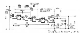
Thyristor welding rectifier
A simplified diagram of a universal thyristor welding rectifier is shown below.
A thyristor is a controlled diode. Externally, a thyristor looks the same as a diode, but has an additional control electrode through which it receives control signals and which unlock (open) it at a given moment in the voltage half-cycle. This moment is called the thyristor firing angle. The thyristor is locked automatically (on its own) at the end of the voltage half-cycle, i.e. when the voltage across it drops to zero. Regulation of voltage and current at the output of the power source is carried out by changing the firing angle of the thyristor. The smaller the thyristor firing angle, i.e. the more of the voltage half-cycle it is open, the higher the current strength at the rectifier output. When using large firing angles of the thyristor, the value of the output parameters decreases while their pulsations increase. To reduce voltage and current ripple, large inductors are installed at the output of thyristor power supplies. Inductance is an effective means of smoothing electrical signals, but at the same time, it degrades the dynamic properties of the power source.
Thyristor rectifiers are, as a rule, universal, i.e. such that provide both falling and flat falling external current-voltage characteristics and thus can be used both for manual arc welding with coated electrodes, and for semi-automatic and automatic welding in shielding gases and submerged arcs.
Finish coatings
When deciding to install electric heated floors in a room, you should consider some points:
- what role will the warm floor play (main heating or additional);
- what finishing coat will be used;
- what is the permissible height of raising the floor level.
In this case, it is the finishing coating that plays a key role in the selection, since not all types of coatings and heating systems are compatible with each other.
Tile
electric heated floor under tiles
- self-regulating and resistive cables;
- rod mats;
- cable mats.
However, tiles do not combine well with IR films, since the film material reacts with the tile adhesive.
Laminate
The advantages of parquet and laminate are their reliability and resistance to wear.
The disadvantages when used as a finishing coating over an electric heated floor is the danger of overheating in certain areas, which leads to a change in the appearance and characteristics of the coating.
They are compatible with almost all types of electric floors. Although the film system is the most preferable, since its installation is easy and quick, and heating is as uniform as possible. The best cable system is a self-regulating cable.
Linoleum
The advantages of linoleum are:
- low cost;
- ease of installation;
- variety of colors and characteristics;
- wear resistance.
The disadvantages include:
- low resistance to mechanical damage;
- danger of overheating from heating systems, which leads to deformation and changes in characteristics.
Self-regulating cables and rod mats are best combined with linoleum. They do not overheat and provide optimal temperature conditions for the coating. Infrared film flooring is also excellent for laying under linoleum.
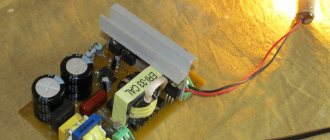
Basic properties of welding inverters
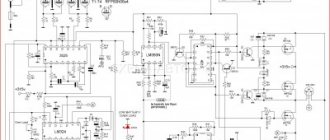
Recently (starting around the beginning of the 80s of the twentieth century), welding inverter power sources have become increasingly widespread. The main unit of such a rectifier is an inverter - a device that converts direct voltage into high-frequency alternating voltage.
The welding inverter works as follows. The network rectifier unit converts the alternating voltage of the network into direct voltage. This rectified voltage is then converted by an inverter into single-phase high-frequency alternating voltage (up to 50 kHz and above). Next, the voltage is lowered by a transformer, rectified again, smoothed out and fed to the arc. Due to the fact that the inverter output voltage has a high frequency, the size and weight of the transformer can be dramatically reduced, since the transformation efficiency increases with the frequency of the alternating current. This also reduces the length of the wire of the primary and secondary windings. The figure below shows this using the example of a 20 kW transformer: in one case the transformer is designed to operate at a frequency of 50 Hz, and in the other - 50 kHz
Due to the low weight and size of the step-down transformer, inverter power supplies are also small in size and lightweight, which, in fact, is the main advantage of these sources. They are recommended for use in cases where small weight and dimensions are important - when welding during installation, at home, during repair work.
Another advantage is their versatility, since their external current-voltage characteristics can be of any shape, since they are formed artificially using a control system using current and voltage feedback (i.e. in real time).
Due to their high dynamic properties (i.e. high speed) and the ability to control welding parameters in real time, these power supplies have better welding properties compared to other types of power supplies, and are often equipped with additional functions that help improve the welding process, such as remote control, soft start, etc.
7.6.32
When water cooling elements of electric welding installations, it must be possible to monitor the condition of the cooling system using funnels for water drainage or jet relays. In water cooling systems of automatic (semiautomatic) machines, it is recommended to use pressure, jet or temperature switches (the last two are used at the water outlet from cooling devices) with their operation on a signal. If stopping the flow or overheating of the cooling water can lead to emergency damage to the equipment, automatic shutdown of the installation must be ensured.
In water cooling systems in which potential that is dangerous for operating personnel can be transferred through pipelines, insulating hoses must be provided (the length of the hoses is selected in accordance with the requirements of 7.5.39).
It is recommended to place detachable connections and hoses of the water cooling system in such a way as to prevent the possibility of a jet of water from hitting electrical equipment (welding power source, etc.) when removing or damaging the hoses.
The quality of water used in the water cooling system must meet the requirements given in Table 7.5.13, unless other standard values are given in the standards or technical specifications for the relevant equipment.
Data plate for welding machines
In accordance with the standard DSTU IEC 60974-1 “Equipment for arc welding” Part 1 “Power sources for welding” (“Arc welding equipment” Part 1: “Welding power sources”) the following symbols of types of welding power sources are introduced.
| Single phase transformer | |
| Single-phase or three-phase rectifier | |
| Single phase or three phase inverter rectifier |
In accordance with this standard, the following symbols for the main welding methods and the type of welding current are also introduced.
| Manual arc welding with coated electrodes |
| Manual arc welding with a non-consumable electrode in inert gas |
| Arc welding in an inert and active gas environment with a consumable electrode, including flux-cored wire (MIG/MAG) |
| Arc welding with self-shielded flux-cored wire |
| Submerged Arc Welding |
| Plasma cutting |
| Plasma gouging |
| D.C |
| Alternating current |
In accordance with the DSTU IEC 60974-1 standard, the technical data plate must indicate: rated welding current, arc voltage, PR (PN), as well as no-load voltage, requirements for the power supply network, VVC form, insulation class and other technical information about the source nutrition.
7.6.11
Electrical receivers of the main equipment and auxiliary mechanisms of electric welding installations in relation to ensuring the reliability of power supply, as a rule, should be classified as electrical receivers of categories III or II (see Chapter 1.2).
Category III should include electrical receivers of all mobile and portable electric welding installations, stationary electric welding installations listed in 7.5.8, workshops and areas, as well as other workshops and areas, if a break in the power supply to the electric welding equipment used in them does not lead to a massive undersupply of products, downtime of workers and machinery.
Efficiency.
Welding is always accompanied by the release of a large amount of heat, which is used to melt the parts being welded. Almost all consumed electrical energy is transformed into thermal energy, with the help of which the metal melts and the surrounding air is heated.
The efficiency in any welding operation has different values and largely depends on the brand of electrodes, the chemical composition of the flux, the type of welded joint and the speed of welding.
To obtain high-quality welds, when organizing the welding process, it is imperative to take into account all the characteristics of the welding arc and control them during operation. This will optimize the entire process and minimize side energy costs. Compliance with all parameters of the welding arc for the selected type of welding is a necessary condition for ensuring high quality work. In addition, this will ensure a long service life of the connected structures.