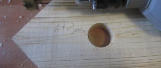
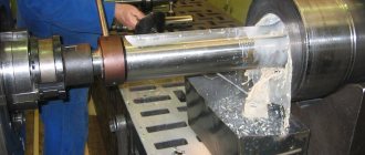
Square-shaped holes in workpieces or products made of metal and other materials can be produced using a cutting tool called a square hole drill. It has another name - Watts drill. Square holes are obtained with slight roundings in the corners, which are almost invisible. They are drilled, reamed and drilled into ferrous and non-ferrous metal with a thickness of no more than 16 mm, wood, plywood and other materials, including substances of composite origin. The operation is performed using a drill, hammer drill, or on lathes or broaching machines. They are used in industry, agriculture and everyday life in the manufacture of products, repairs and DIY crafts.
About Watts drill and Reuleaux triangle
In order to understand how the Watts drill works, you need to take a short excursion into geometry. Back in the 15th century, mathematicians became interested in the interesting properties of flat figures with equal thickness. The most famous such figure is the circle. Another simple shape from this series is a rounded triangle.
This figure turns out like this. An equilateral triangle is taken as a basis. Then a circle with a radius equal to the side of the triangle is drawn from each vertex of the triangle. The result will be a new shape with arched sides (see picture below).
A little later, the scientist L. Euler drew attention to the interesting trajectory of rotation of a rounded triangle. Then the engineer Reuleaux saw that with a certain way of rotating the figure, the trajectory of its vertices describes a shape very close to a square. To do this, it is necessary to rotate with some eccentricity. With this movement, minor roundings are formed only in the inner corners of the resulting square. Such a triangle is today known as the Reuleaux triangle.
At the beginning of the 20th century, the English scientist Watts was able to invent and patent a technical solution that would ensure such movement of a metal-cutting tool that it would ultimately result in a square hole in the workpiece. The resulting tool became known as the Watts drill.
History of the instrument
The design of the Watts drill is based on the Reuleaux triangle. To obtain such a figure, you need to draw an equilateral triangle and three circles. Their centers are located at the corners of the triangle, and the radius is equal to its side. The result is a triangle with rounded sides. An engineer from Germany, F. Relo, noticed that with certain methods of rotation, the new figure’s trajectory is as close as possible to a square.
Reuleaux triangle:
In 1916, Watts filed a patent for a special device. His technical development ensured that the drill moved in such a way as to guarantee square-shaped holes.
Watts drill:
Classification of drills for square holes
In modern metalworking, almost all cutting tools that are used to produce square holes work on the principle of rotation of the Reuleaux triangle. A Watts drill (or as it is sometimes called a Reuleaux drill) allows you to make square holes of various sizes in metal parts of various thicknesses. This tool is classified according to its size, material of manufacture, and shank design.
A Watts metal drill must be made of high-speed steel. This tool is marked HSS (High Speed Steel). For domestically produced tools, tool steel U10 or alloy steels X12 and X12MF are used. The hardness of the tool should be between 52 and 60 HRC. A square drill can have different diameters depending on the size of the side of the square.
Note that buying a Watts drill is quite difficult. Don't expect it to be available in every hardware store. You may have to purchase it to order from a large tool store or buy it from an online store.
A little history with geometry
The peculiarity of such a triangle will be that all its sides will have a constant width, which is equal to the length of the side of the original equilateral triangle.
L. Euler drew practical benefit from this fact, who three centuries later demonstrated the rotation of such a rounded triangle: first around its own axis, and then with some eccentricity, since the cardan mechanism was already known to science and technology of that time.
The German engineer F. Relo went even further in the practical use of this figure, who drew attention to the fact that the trajectory of the corners of a moving triangle with certain methods of its rotation is very close to a square.
Only directly at the corners of the square does the outer surface describe an arc, however, of a small radius. In modern technical literature, such a triangle is called the Reuleaux triangle, although this figure actually no longer has any angles.
A few more decades will pass, and the Englishman G. Watts will come up with a device that can provide a guaranteed square trajectory for a metal-cutting tool. The technical solution for the Watts drill was patented in 1916, and a year later mass production of such tools began.
Drill or cutter?
The majority of the technical community believes that it is still a milling cutter. However, manufacturers stubbornly continue to call this tool a drill for square holes, a Watts drill, or a drill whose profile corresponds to the Reuleaux triangle.
Which is more correct? If we turn to the kinematics of movement of such a cutting tool (for clarity, you can use the diagram shown in Fig. 1), you will find that metal removal will be carried out only by the side surface, and there will be not one cutting plane, like a conventional drill, but four, which more typical for cutters.
However, a single rotating motion will not be enough to obtain a square hole.
Simple mathematical calculations (not given in this article) show: in order for a “drill” for a square hole to perform its function, during operation it must describe not only the basic rotational movement of the cutting edge, but also the rocking movement of the drill/cutter around a certain axis. Both movements must be made in mutually opposite directions.
Figure 1 – Reuleaux Triangle: a) – construction; b) rotation sequence to obtain a square-shaped hole.
The angular velocity of both rotations is determined quite simply.
If we take the rotation frequency of the drill shaft (or hammer drill) as the parameter f, then a speed of 0.625f is sufficient for oscillatory rotations of the spindle around its own axis.
In this case, the spindle axis is, as it were, clamped between the working shaft and the drive wheel, causing the drill/cutter to oscillate in the clamping device with a residual speed
(1 – 0.625)f = 0.375f.
The resulting rotation speed of the cutter can be more accurately determined using the technical characteristics of the drill/hammer, but it is clear that it will be much lower than that for which the tool was originally designed. Therefore, obtaining a square hole will occur with less productivity.
Design and principle of operation
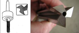
It is impossible to directly use a cutter/drill for square holes with a Reuleaux triangle profile - grooves are needed to remove the resulting chips.
Therefore (see Fig. 2) the profile of the working part of the tool is the figure described above, from which three half-ellipses are cut out. In this case, three goals are realized: the moment of inertia of the drill and the load on the spindle are reduced, and the cutting ability of the cutter is increased.
Figure 2 – Actual profile of the working part of the tool
The design of the tool is as follows. Actually, the working part includes a working surface used to remove metal and grooves that remove chips.
A cutter-drill for square holes is made from U8 steel and hardened to a hardness of HRC 52...56. Under particularly severe operating conditions, products made of X12 alloy steel with a hardness of HRC 56...60 are used.
With normal coolant supply and due to relatively low temperatures in the processing zone, tool life is high.
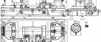
The adapter spindle has a more complex design. It includes:
- Frame.
- Ring gear.
- A seat for the main spindle (if the tool is installed in the tool head of a metal-cutting machine, then the adapter has the form of a Morse cone).
- Drive gear.
- Main spindle.
- Meshing gears with a ring gear.
- Oscillating bushing.
For household devices, manufacturers of cutters/drills for square holes offer overhead frames that are connected by a cardan drive to the chuck and impart eccentric movements to the cutting tool. The thickness of this frame determines the depth of the resulting hole.
To connect the device to the machine chuck, a special adapter is also required. It consists of:
- Cases.
- Floating shank.
- Swinging ring.
- Replaceable bushings for cartridges of various metalworking machines.
- Mounting screws.
- Support balls.
For the practical use of the tool in question, it is enough to give the spindle of the main equipment a feed in the required direction. Broaching milling machines and lathes are suitable for making square holes using such equipment.
Alternative Methods for Making Square Holes
The disadvantage of Watts drills is the presence of radius arcs in the corners of the square, which is not always acceptable. In addition, square hole drills made using the Reuleaux triangle cannot handle thick workpieces.
In such cases, you can use electroerosive/laser technologies, and also, which is easier, use welding or stamping.
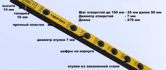
Sets of punches for square holes are produced in an assortment of transverse sizes up to 70×70 mm in metal with a thickness of up to 12...16 mm. The kit includes:
- Punch holder for punch.
- Guide bushing.
- Ring travel stop.
- Matrix.
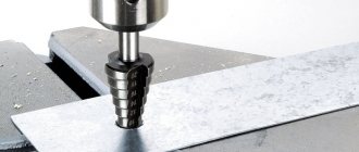
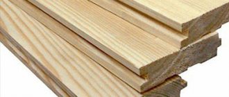
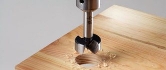
Features of drilling square holes in wood
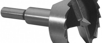
In furniture production, parts are often connected using a tongue-and-groove system. This connection assumes the presence of square grooves in the supplied parts. To make holes in wood, use a special square wood drill. It is a set of slotting tools. It consists of an internal wood drill and a chisel that fits onto it. Typically, the drill diameter ranges from 6 to 18 millimeters. The shank usually has a diameter of 19 millimeters. Such kits can be installed on slotting and drilling machines.
The principle of operation and design of the Watts drill
Drilling square holes using a Watts drill is based on the principle of rotational movement of the Reuleaux triangle along a specific eccentric trajectory.
The shape of the drill does not exactly follow the rounded triangle, but its cutting edges fit into its shape.
The drill has such a shape of cutouts in order to remove chips from the working area, as well as to minimize the moment of inertia of the tool. In addition, reducing the weight of the tool helps reduce the load on the spindle of the metal-cutting machine, and sharpened edges increase the cutting capabilities of the drill.
In addition to the Watts drill, the work will definitely require an adapter spindle, which will provide an alternating displacement of the center of the tool and set the trajectory required for the work.
It consists of an adapter for connection to the machine spindle, a ring gear, a drive gear and an engagement gear, as well as oscillating bushings. To use a square drill with household power tools, manufacturers produce special attachment templates with a cardan drive.
Geometric parameters
The main geometric parameters include the following indicators:
- diameter indicated in mm;
- total length, mm;
- length of the working part, mm;
- sharpening angle in degrees.
In addition, when choosing a square drill, pay attention to the shank, which must match the tool spindle or a set of devices for fastening it. Drilling square holes must be done after preliminary marking and punching the center of the future hole. It is recommended to start drilling at low rotation speeds, and then switch to the speed indicated in the data sheet of the machine or tool.
Operating principle and design of the Reuleaux triangle
The Reuleaux triangle is a flat geometric figure. It is formed by connecting the vertices of an equilateral triangle with circular arcs drawn from each vertex of the same triangle.
The peculiarity of the Reuleaux triangle is that when performing a rocking motion, its vertices describe the trajectory of an almost perfect square.
The only drawback of this rotation of the Reuleaux triangle is that small roundings remain in the corners of the square.
If it is necessary to obtain a square hole with internal angles of 90 degrees, it will have to be modified. This can be done manually using files and rasps or on a slotting machine.
Laser cutting of holes in metal
In this section, we are not going to talk about the advantages of laser cutting, for example, such as minimum material waste or high speed. We will give only important information regarding cutting holes and windows in metal.
- The work is carried out exactly according to the project.
Unlike a drill, the laser beam cannot be directed when cutting; it is directed only in the indicated direction, in a straight line. Compared to a plasma arc, the beam does not move from side to side. The process is controlled by a robot (CNC - numerical control), which cannot be distracted or relax after making a mistake, like a human.
Thanks to CNC, the parts completely correspond to the design, the size of the holes will be the same. With a correctly written program, all manufactured parts correspond to the original design.
- Outlines of almost any complexity.
Let's look at an example. Currently, the fastest and cheapest method is coordinate punching, which allows you to make windows with regular outlines. The edges may not be completely straight, parts of the product are sometimes damaged, but the cost of such production is significantly lower than laser cutting. However, we are talking about windows with standard outlines.
The coordinate machine has a punching element whose shape is predetermined. Like molds for playing in a sandbox. If you have a square shape, it is impossible to make a round Easter cake. You need to order a round mold first. In principle, this is possible. However, what to do if you need an Easter cake in the form of a company logo... You can order a mold for making a logo, however, production will no longer be cheap or fast.
A laser machine is able to cut out a figure of both standard and the most complex configuration. The operator sets a program during which the beam moves in the desired direction. In this case, the intricacy of the drawn form does not matter.
- The minimum hole diameter is more than 1 mm.
Another important point is the accuracy of the cutting. When working with a plasma device, which also makes cutting according to coordinates, the corners are rounded. The problem lies in the cross-sectional thickness of the plasma arc, which is larger than the laser beam. A plasma arc can be used to cut complex shapes, but in fact they may not exactly correspond to those planned.
VT-metall offers services:
The same applies to the minimum hole size. The diameter of the circle cut by a laser beam is equal to the thickness of the material and cannot be less than 1 mm. The diameter of the hole cut by the plasma arc is equal to the thickness of the material multiplied by 1.5, but not less than 4 mm.
- High quality hole edges.
Laser cutting of holes in metal makes the edges of the material as close to perfect as possible. When plasma cutting, the edges are not vertical enough, and when punching, they bend slightly.
Despite being close to ideal, the edges of the metal still do not quite match it. When laser cutting relatively thick metal sheets, the holes also have a slight taper, that is, the entrance diameter is slightly smaller than the exit diameter. But only for fat people. Laser cutting mainly involves sheets of material with a thickness of 1, 2, 4 mm, and the taper on them is quite difficult to distinguish.
- What metal is suitable for cutting holes.
The type of metal affects the maximum possible thickness of the sheet in which a hole can be cut:
- Black steel – < 16 mm.
- Aluminum – < 10 mm.
- Stainless steel – < 10 mm.
- Brass – < 5 mm.
- Titanium – < 5 mm.
- Galvanized steel – < 3 mm.
- Is it possible to cut perforations with a laser?
When producing doors, panels or cabinets, it is sometimes necessary to perforate metal. Perforation is holes scattered on a plane, sometimes made in the form of a pattern, which are necessary for ventilation. Is a laser machine capable of making it?
I guess, yes! But this is not very economically feasible. The reason lies in the fact that it is cheaper and easier to make holes with a punching machine, because one blow will be enough for it. The laser beam must cut each hole. Their close location, a long cut can lead to overheating of the material and the workpiece will lead. In most cases, laser cutting does not cause the metal to overheat and drag, but when performing perforations this can happen. In addition, laser cutting is unnecessarily expensive.
We recommend articles on metalworking
- Steel grades: classification and interpretation
- Aluminum grades and areas of their application
- Defects in metal products: causes and search methods
If it is necessary to provide the product with perforation, you can proceed as follows: take a ready-made perforated sheet and cut a piece of the required size from it. A piece of the same size is cut out on the main part. Then the punch sheet needs to be inserted into this window. Fastening is carried out by resistance welding.
Alternative options for making a square hole
Although the Watts drill is the most productive and accurate tool for making square holes, there is more to be said about how to drill a square hole using other methods.
There are several good methods for this. When working with square drills, the resulting hole in the workpiece will have small radius roundings, which then need to be eliminated by other operations. In addition, there is no possibility of working with parts of significant thickness.
Let's take a closer look at these methods:
- In production conditions, the most accurate finishing method for cutting a square hole is laser cutting. But for this it is necessary to have expensive complex CNC machines in the equipment park.
- Another method is to drill a round hole in the part with the diameter of a circle circumscribed by a square. Then the corners of the hole are welded with the template inserted. This method requires a welding machine and appropriate skills.
- In mass production conditions, when working with sheet and thin-walled metal, square holes are produced by sheet stamping. In single production this is not relevant, since it requires the manufacture of cutting or punching dies.
- When working at home, if you need a square hole that is not very small in size, then you can drill it in the following way. A round hole with the diameter of a circle inscribed in a square is made in the part using an ordinary metal drill. Then the imaginary corners and edges of the square are straightened using a file and chisel.
- For working with thin metal, special square punches are also available. Their maximum size is 70 by 70 millimeters.
Is it possible to accurately cut holes in metal with plasma?
Plasma can make long cuts, this is confirmed by professionals and is not a new thing. Difficulties arise when making holes using plasma cutting in electrically conductive metals to connect parts with bolts. At the same time, quality raises big questions. Let's consider recommendations that can improve the quality of work and make it easier.
- Plasma height control.
During the cutting process, it is very important to maintain a certain distance between the metal surface and the cutter. It affects the quality of the product and the service life of consumables.
The plasma height must be carefully selected. When cutting, the distance between the cutter and the material being processed must be made slightly larger. General advice: when using plasma, the piercing height should be 50-100% higher than recommended. Let's look at an example: the recommended cutting height is 2-2.5 mm, while a professional will work at a distance of 4-5 mm. It must be remembered that an excessively small distance leads to accelerated wear of the equipment.
- Find a place to burn.
Precisely localizing the initial piercing will help prevent arc oscillation, stretching, and other problems. Firstly, the arc will stabilize before it reaches the edge of the hole. Both energy and pressure must be increased gradually. Secondly, vibrations of the plasma arc, which arise due to the presence of scale on the metal, can be almost completely eliminated by determining the place for punching directly near the center. For combined straight line cutting methods, the same rules apply.
- Control of arc height and voltage.
The low cutting speed inherent in automatic systems affects changes in arc height during the production of holes with a diameter of less than 25 mm. To prevent this, the plasma arc voltage controller is turned off before cutting.