If you need to understand the control of welding joints or you want to know the types of control and when they are used, then you will find all this in our article.
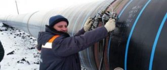
Welding and inspection are inextricably linked. After completing the welding work, any connection must be inspected, regardless of whether it is a fence at the dacha or a main gas pipeline. The only difference will be in the methods used and the scope of control. For the fence, visual control will be sufficient, but the gas pipeline must be additionally checked by ultrasound or x-ray, well, more about everything.
NK
Non-destructive testing (NDT) is control of the reliability and basic operating properties and parameters of an object or its individual elements or assemblies, which does not require the object to be taken out of operation or dismantled.
Non-destructive testing is also called non-destructive reliability assessment or non-destructive testing. NDT is especially important when creating and operating vital products, components and structures. To identify various defects such as corrosion, rusting, cracking.
VIC
Visual and measuring inspection is considered a very effective and convenient way to identify a wide variety of defects. All non-destructive testing activities usually begin with a visual inspection. This type of control is carried out both with and without the use of special devices. The visual inspection method, in particular, has proven its highest efficiency in monitoring the quality of the base metal, welds, joints and surfacing - both in the process of preparing and carrying out welding, and in correcting identified defects.
Compared to many other methods, visual inspection is easy to implement and relatively inexpensive. In practice, it has been proven that this control method is a reliable source of the most accurate information about the compliance of welded products with the required technical conditions. Visually, optical testing differs from other types of non-destructive testing in the boundaries of the spectral region of EMR (electromagnetic radiation) used to obtain information about an object. It can be carried out using even the simplest measuring instruments. Naturally, a lot here depends on the goals, objectives and conditions of the measurement (in some cases it is necessary to use rather complex means of visual control in combination with a high level of qualification of the specialist who carries it out). In addition, visual measuring control is the same reliable type of control as ultrasonic and radiation. Of course, to effectively identify defects, you need to be able to choose the right approach and develop an appropriate inspection technique.
The disadvantage of VIC is the human factor (physical and emotional state of the controller, fatigue, etc.)
Capillary control using kerosene
In earlier times, kerosene was used to find defects. This liquid was widely used in everyday life and technology. Kerosene almost does not evaporate under normal conditions, but has good penetrating ability due to its low viscosity and high polarity.
Because Kerosene is colorless, then welders used chalk and other substances to correctly assess the presence and size of shells, cracks and cavities.
The kerosene method, due to its simplicity, is still used in practice today. Most often, this method is used to search for through defects in pressure tanks; it is also used when testing fuel compartments or products with various welded joints.
Inspection procedure and sensitivity for the kerosene control method:
| Kerosene pressure, Pa | Sensitivity, mm3 MPa/s | Inspection procedure for metal thickness, mm | |
| ≤ 6 | 6 — 25 | ||
| — | 6,6 · 10-2 | 1. Immediately after kerosene is supplied 2. 15-30 minutes after kerosene is supplied | 1. 3-5 minutes after kerosene supply 2. 30-50 minutes after kerosene supply |
| 2,9 · 105 | 6,6 · 10-3 | 1. 1-2 minutes after applying pressure 2. 15-30 minutes after applying pressure | 1. 1-2 minutes after applying pressure 2. 30-40 minutes after applying pressure |
There are four types of control using kerosene:
- Simple kerosene.
- Kerosene using vibration.
- Kerosene using a vacuum.
- Kerosene using pneumatic properties.
A simple kerosene method is that the joint, cooled after welding, is painted on one side with an aqueous suspension of koalin or chalk, after the suspension has dried, the other side is lubricated with kerosene and the reaction is observed.
In the kerosene-pneumatic method, a stream of compressed air at a pressure of about 0.4 MPa is directed onto a surface moistened with a kerosene solution, which increases the sensitivity of the test and speeds up the detection of damage.
With the kerosene vacuum method, the seams of the product are wetted, a vacuum chamber is installed, with the help of which a difference in air pressure is created. As a result, the capillary pressure, together with the air pressure difference, increases the accuracy of the test results.
The kerosene vibration method is carried out using ultrasound. The surface moistened with kerosene begins to be affected by ultrasonic vibrations, this increases its penetrating ability into the compound and thus more accurate results can be obtained.
UK
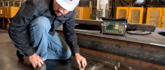
Ultrasonic testing of welded joints is an effective way to identify defects in welds and metal products located at depths from 1-2 millimeters to 6-10 meters. This method allows you to perform the entire range of work on ultrasonic diagnostics of welded joints and reduces the cost of examination.
Ultrasonic testing allows you to diagnose the quality of welded joints, control metals, castings, steel castings and much more.
Ultrasonic testing allows you to identify and document areas of high defect content, classifying them by type and size. For different types of welded joints, appropriate ultrasonic testing techniques are used. When ultrasonic testing of welded joints, pulse-echo, shadow or echo-shadow ultrasonic testing . The method of ultrasonic testing of a welded joint is established in the technical documentation.
Ultrasonic testing of welded joints allows for complete diagnostics of welded joints without the use of expensive methods of non-destructive quality control of welded joints.
PVC testing of welded joints for permeability
Some products using welding must be strictly sealed, since various liquid substances will be stored inside them: water, oil, fuels and lubricants, etc. Therefore, special attention is paid to the permeability of seams in these structures.
Permeability control is often carried out in two ways: hydraulic and pneumatic.
Hydraulic method for checking the permeability of welded joints
The container, which must be sealed, is filled with water or oil, and excess pressure is created in it, which is one and a half times more than the standard one.
Then, for 10-30 minutes, the areas around the welds are tapped with a hammer with a rounded head, in the expectation that if there is a through welding defect, a leak will appear.
Pneumatic testing method
Any gas is pumped into the container until the pressure reaches 150% of the nominal pressure. After injection, the welded joints are treated with a soap solution. The bottom line is that if there are through defects in the seams, then bubbles will begin to form on the surface of the soap solution, which will clearly reflect the presence of damage.
If it is impossible to pump gas into the tank, the seam is blown under pressure on one side and treated with a soap solution on the other. If a defect exists, bubbles will appear in the solution again.
PVK
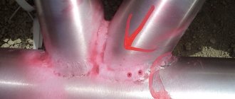
Penetrant flaw detection is a flaw detection method based on the penetration of certain liquid substances into surface defects of a product under the action of capillary pressure, as a result of which the light and color contrast of the defective area relative to the undamaged area increases.
Penetrant testing is designed to identify invisible or weakly visible to the naked eye surface and through defects (cracks, pores, cavities, lack of fusion, intercrystalline corrosion, fistulas, etc.) in test objects, determining their location, extent and orientation along the surface.
There are luminescent and color methods of capillary flaw detection.
In most cases, according to technical requirements, it is necessary to identify defects so small that it is almost impossible to notice them during visual inspection with the naked eye. The use of optical measuring instruments, such as a magnifying glass or a microscope, does not allow identifying surface defects due to insufficient contrast of the image of the defect against the background of the metal and a small field of view at high magnifications. In such cases, the capillary control method is used.
During capillary testing, indicator liquids penetrate into the cavities of surface and through discontinuities in the material of the test objects, and the resulting indicator traces are recorded visually or using a transducer.
Procedure for training in control of PVC and PVT
- The student undergoes full-time training or distance learning to the extent provided for by SDANK-02-2020 to study methods of control with penetrating substances.
- During the learning process, he is provided with educational and methodological material, and performs practical work in the amount of at least 50% of the total number of hours.
- Before certification, the student submits documents on experience and education, and a medical certificate.
- Certification is carried out in the form of an exam in three parts: general, special NDT method, Safety Rules.
- After passing the exam, the student receives a NOAP certificate and is included in the register of NK specialists.
MK
Magnetic non-destructive testing methods are used to identify defects in parts made of ferromagnetic materials (steel, cast iron), i.e. materials that can significantly change their magnetic characteristics under the influence of an external magnetic field.
Magnetic non-destructive testing is based on identifying stray magnetic fields arising above defects in various ways, or on determining and assessing the magnetic properties of the test object.
The magnetic particle method is based on identifying stray magnetic fields that arise above defects in a part when it is magnetized, using ferromagnetic powder or a magnetic suspension as an indicator. This method, among other magnetic testing methods, has found the greatest application. Approximately 80% of all parts made of ferromagnetic materials subject to inspection are checked using this method. High sensitivity, versatility, relatively low labor intensity of control and simplicity - all this ensured its widespread use in industry in general and transport in particular. The main disadvantage of this method is the complexity of its automation.
Thermal method of non-destructive testing
Thermal/infrared testing is used to measure or display surface temperature based on the infrared radiation emitted by an object as heat passes through or out of that object. Most infrared radiation is longer wavelength than visible light, but can be detected using thermal imaging devices (thermal cameras) called "infrared cameras." For accurate IR testing, the part being tested must be in direct line of sight to the camera and should not be covered by foreign objects or a cover, as covers will dissipate heat and may cause false readings. When used correctly, thermal imaging can be used to detect corrosion damage, deposits, voids, inclusions, and many other defects and abnormalities.
RK
Radiation monitoring methods are based on registration and analysis of ionizing radiation during its interaction with the controlled product. The most frequently used methods for testing by transmitted radiation are based on different absorption of ionizing radiation when passing through a defect and a defect-free area of a welded joint. The intensity of transmitted radiation will be greater in areas of smaller thickness or lower density, in particular in places of defects - discontinuities or non-metallic inclusions.
Radiation monitoring methods are classified primarily by the type (and source) of ionizing radiation and by the type of ionizing study detector.
Ionizing is a study whose interaction with the environment leads to the formation of electrical charges. Since ionizing radiation, consisting of charged particles, has low penetrating ability, photon or neutron radiation is usually used for radiation testing of welded joints. The most widely used is X-rays (X-rays). This is photon radiation with a wavelength of 6x10-13...1x10-9 m. Having the same nature as visible light, but a shorter wavelength (visible light has 4...7 x 10-7 m), X-ray radiation has a high penetrating ability and can pass through fairly large thicknesses of structural materials. When interacting with the material of the controlled product, the intensity of the x-ray radiation decreases, which is used during testing. X-ray radiation provides the greatest sensitivity of monitoring.
X-rays are produced in X-ray tubes. Electrons emitted from the heated cathode under the influence of high voltage are accelerated in a sealed cylinder from which air has been evacuated and fall on the anode. When electrons are decelerated at the anode, their energy is released in the form of photons of various wavelengths, including x-rays. The greater the accelerating voltage, the greater the energy of the generated photons and their penetrating ability.
The disadvantages of radiation methods include, first of all, the harm to humans, which requires special radiation safety measures: shielding, increasing the distance from the radiation source and limiting the time the operator stays in the hazardous area. In addition, radiation methods poorly detect small-opening discontinuities (cracks, lack of penetration) located at an angle of more than 7 ... 12° to the direction of transmission; the method is ineffective for fillet welds.
Radiation control
Radiation monitoring (RM) is used for the most critical facilities, where high demands are placed on the quality of welding. The number of joints (% of inspection) that must be inspected by x-ray is determined by the regulatory documents for the object of inspection. For process pipelines, for example, such a document is GOST 32569.
Most often, the following methods are used for radiation monitoring:
- Radiographic
- Gammagraphic
The radiographic method uses an X-ray machine, which is located on one side of the controlled object, and a film (also known as a detector) is installed on the other.
During operation, the device produces radiation (X-rays), which passes through the metal and forms an image on the film. The image can be viewed only after processing in chemical reagents and subsequent drying.
X-ray machines are divided into 2 types:
- Pulse.
- With constant potential.
Pulse ones are cheaper, have less weight and dimensions. Typically used for thin products and small pipe diameters. Since the radiation from such devices (integral dose) is low.
Devices with a constant potential are more accurately adjusted and are most often used for thick-walled structures. Compared to pulse devices, such devices are heavier and larger, and their maintenance is much more expensive.
The gammagraphic method assumes that instead of an X-ray machine (radiation generator), a gamma radiation source will be used containing radioactive elements such as: Iridium - 192; Selenium - 75; Cesium - 137 and so on. Using this method, a product with a wall thickness of up to 300–400 mm can be illuminated.
Gamma sources are used only for thicknesses over 50 mm, since smaller thicknesses do not create sufficient resistance and the image is of low clarity. These devices are a closed, impenetrable container containing a hermetically sealed ampoule containing a radioactive isotope.
TK
Thermal control is based on measuring, monitoring and analyzing the temperature of controlled objects. The main condition for the use of thermal control is the presence of heat flows in the controlled object. The process of transferring thermal energy, releasing or absorbing heat in an object causes its temperature to change relative to the environment. Temperature distribution over the surface of an object is the main parameter in the thermal method, as it carries information about the features of the heat transfer process, the operating mode of the object, its internal structure and the presence of hidden internal defects. Heat flows in a controlled object can arise for various reasons. Thermal imaging technical diagnostics have become widespread in the energy sector, construction and industry. The main advantage of the method is the control of objects without decommissioning and without any impact on them. It is obvious that the successful implementation of the thermal control method is facilitated by the development of measuring instruments, mainly thermal imaging equipment.
The use of thermal imagers is not limited to non-destructive testing tasks. This wonderful tool for visualizing thermal fields and remotely measuring temperature has found application in military technology, navigation, medicine, safety and security systems, fire fighting, and ecology.
Methods of penetrant inspection of welds
There are basic and combined methods. The main one is control, which is carried out only by capillary penetration of special substances into the compound. Then it is logical that the combined method includes those examinations where control is carried out by two or more non-destructive testing methods.
Combined control methods
Such methods can be classified depending on the method of exposure to the test compound.
- Capillary-magnetic.
- Capillary radiation method.
- Capillary-electrostatic.
- Capillary-radiation absorption method.
- Capillary-induction.
HTP
Leak detection is the process of detecting leaks.
Standardization of leak detection methods today not only meets the formal need to develop and apply the most correct methods and techniques for monitoring the tightness of products, installations, and systems, but also becomes a practically necessary measure due to a number of circumstances. These include:
- increasing requirements for the reliability of operation of facilities that pose a danger to the population and the environment in the event of accidents,
- development of leak detection instrumentation, both foreign and domestic, providing new opportunities for their use,
- the relative complexity of performing leak tests, requiring special knowledge and skills,
- limited distribution of leak detection experience, which was accumulated mainly in defense and closed industries,
- ineffectiveness of blindly spreading the experience of monitoring some objects to others belonging to a different class of technical systems.
Leak detection in vacuum technology, detection of leaks in vacuum systems. This is done with devices called leak detectors. The simplest way to find leaks is using a spark leak detector, which detects leaks in glass shells by the spark that occurs when the leak detector needle touches the defective area. The smallest leakage is estimated at 10-4 n×m/sec, or 10-3 l×mmHg. art./sec. To detect more “subtle” leaks in any shells (glass, metal, etc.), mass spectrometric leak detectors are used. Leakage is determined by the penetration of a test substance (usually He) into the system, with which it is blown from the outside. A mass spectrometer configured to indicate He is included in the vacuum system and the presence and size of a leak is judged from the readings of its recording device. A helium leak detector detects leaks of 10-15 n×m/sec, or 10-14 l×mm Hg. Art./sec. Other test substances are also used (for example, Ar).
The action of a halogen leak detector is based on the property of some metals (for example, Pt, Ni), which emit ions of alkali metal impurities when heated, to increase emission in the presence of halogens (halogen effect causing surface ionization). Freons are most often used as test substances. The change in ion current determines the presence and size of a leak. Halogen leak detectors detect leaks up to 10-9 n×mm Hg. art./sec, or 10-8 l×mm Hg. art./sec. Other leak detection methods are less common: luminescent, tagged atoms, etc.
§ 43. Flaw detector for gas and liquid testing (2nd category)
Characteristics of the work . Preparation of controlled products for testing. Blowing and blowing air onto the surfaces of the product and vacuum systems, wiping vacuum hoses and outlet pipes of vacuum systems with alcohol. Application and removal of penetrating fluid and absorbent coatings. View the product under ultraviolet rays. Switching on and off helium and halogen leak detectors to operating modes. Checking the response to helium of leak detectors using quartz diffusion leakage. Connecting helium cylinders and reducers to the helium system. Measuring excess gas pressure and vacuum in systems using electrical and mechanical instruments. Operation of mechanical and steam jet vacuum pumps.
Must know: basic information about obtaining a vacuum; operating principle of mercury-quartz lamps, fluorescent devices, pumps: vane-rotor, vane-stator, spool-plunger, steam-jet and cooled traps; purpose and conditions of use of instrumentation for measuring vacuum; design and principle of operation of paint sprayers; helium and halogen leak detectors; methods used in monitoring the tightness of structures with leak detectors.
Work examples
1. Castings, forgings and stamped blanks of simple configuration - control with ultraviolet rays.
2. Instruments for measuring excess pressure and vacuum - taking readings from pressure gauges, mechanical and electronic vacuum gauges.
3. Butt welded joints - control with ultraviolet rays.
4. Leak detector - preparing the device for operation and starting it up.
VD
Vibration diagnostics is a method for diagnosing technical systems and equipment, based on the analysis of vibration parameters, either created by operating equipment, or secondary vibration caused by the structure of the object under study.
Vibration diagnostics , like other methods of technical diagnostics, solves the problems of troubleshooting and assessing the technical condition of the object under study.
The method has received the greatest development in diagnosing rolling bearings. The vibration method is also successfully used in the diagnosis of wheel-gear units in railway transport.
Vibroacoustic methods for searching for gas leaks in hydraulic equipment also deserve attention. The essence of these methods is as follows. A liquid or gas, throttling through cracks and gaps, creates turbulence, accompanied by pressure pulsations, and, as a result, harmonics of the corresponding frequencies appear in the spectrum of vibrations and noise. By analyzing the amplitude of these harmonics, one can judge the presence (absence) of leaks.
The intensive development of the method in recent years is associated with the reduction in the cost of electronic computing tools and the simplification of the analysis of vibration signals.
Advantages:
- the method allows you to find hidden defects;
- the method, as a rule, does not require assembly and disassembly of equipment;
- short diagnostic time;
- the ability to detect faults at the stage of their inception.
Flaws:
- special requirements for the method of mounting the vibration sensor;
- the dependence of vibration parameters on a large number of factors and the difficulty of isolating a vibration signal caused by the presence of a malfunction;
- low diagnostic accuracy.
Visual and optical testing as methods of non-destructive testing
Visual testing is the most commonly used testing method in industry. Because most testing methods require the operator to look at the surface of the part being tested, visual inspection is inherent in most other testing methods. As the name suggests, visual inspection involves visual observation of the surface of the object being examined to assess the presence of visible defects and deviations. Visual inspections may be performed by direct vision inspection or may be enhanced by the use of optical instruments such as magnifying glasses, mirrors, borescopes, video endoscopes, and computer viewing systems.
A portable video surveillance unit with zoom allows you to inspect large tanks and ships, railway tanks, and sewer lines. Robotic scanners allow surveillance in hazardous areas such as air ducts, reactors, and pipelines. Corrosion, misalignment of parts, physical breaks and cracks are just some of the defects that can be detected using visual and optical testing technology.
EC
Electrical methods of non-destructive testing are based on the creation of an electric field on the controlled object, either by direct exposure to an electrical disturbance, or indirectly through thermal, mechanical influence. Using electrical control, the parameters of the electric field are recorded.
Electrical testing records the parameters of the electric field interacting with the controlled object (electrical method itself), or the field arising in the controlled object as a result of external influence (thermoelectric method) and is used to control dielectric and conductive materials.
Electrical testing methods (electrostatic powder, thermoelectric, electric spark, electric potential, capacitive) make it possible to determine defects in various materials, measure the thickness of coatings and layers, sort metals by grade, and control dielectric or semiconductor materials. The disadvantages of the listed electrical NDT methods are the need for contact with the test object, strict requirements for the cleanliness of the product surface, difficulties in automating the measurement process, and the dependence of measurement results on the state of the environment.
Comparison of non-destructive testing methods
No single NDT method will work for all defect detection or measurement applications. Each method has advantages and disadvantages compared to other methods. The table below summarizes the main types of non-destructive testing, common applications, and the advantages and disadvantages of some of the most commonly used non-destructive testing methods.
| Methods of non-destructive testing with penetrant substances | Magnetic non-destructive testing methods | Acoustic methods of non-destructive testing | Eddy current non-destructive testing methods | Radiation methods of non-destructive testing | |
| Main Use | |||||
| Used to detect cracks, porosity and other defects that are on the surface of a material and have sufficient volume to fill and retain the penetrating material. | Used to test ferromagnetic materials (those that can be magnetized) for defects that result in a transition in the material's magnetic permeability. Magnetic particle inspection can detect surface defects | Used to detect surface and internal defects in many materials, including metals and plastics. Ultrasonic testing is also used to measure the thickness of materials and in other cases characterizes material properties based on sound speed and attenuation measurements. | Used to detect surface and near-surface defects in conductive materials such as metals. Eddy current testing also measures the thickness of thin sheets of metal and non-conductive coatings such as paint. | Used to test almost any material for internal defects. X-rays can also be used to detect and measure internal characteristics, confirm the location of hidden parts in an assembly, and measure the thickness of materials. | |
| Main advantages | |||||
| Large surface areas or large volumes of parts/materials can be inspected quickly and inexpensively. Parts with complex geometries are inspected regularly. Readings are taken directly on the surface of the part, providing a visual image of the break. Investment in equipment is minimal. | Large surfaces of complex parts can be inspected quickly. Can detect surface and near-surface defects. Magnetic particle readings are made directly on the surface of the part and form an image of the fracture. The cost of the equipment is relatively low. | Penetration depth for defect detection or measurement is superior to other methods. Only one-way access is required. Provides information about the depth of the defect. Part preparation required. The method can be used for much more than just detecting defects. | Detects surface defects. The sensor does not need to be in contact with the workpiece. The method can be used to detect various defects. Minimal preparation of the part is required. | Can be used to test almost all materials. Detects hidden internal defects. Ability to test complex shapes and multi-layer structures without disassembly. Minimal preparation of the part is required. | |
| Flaws | |||||
| The method detects only surface fracture defects. Surface preparation is critical as contaminants can mask defects. A relatively smooth and non-porous surface is required. | Only ferromagnetic materials can be tested. Correct alignment of the magnetic field and the defect is critical. Large currents are needed for very large parts. A relatively smooth surface is required. | The surface must be accessible to the probe and coupling. Surface and roughness may interfere with testing. Linear defects oriented parallel to the sound beam may go undetected. | Only conductive materials can be tested. Ferromagnetic materials require special treatment to eliminate magnetic permeability. Penetration depth is limited. Flaws that lie parallel to the direction of the inspection probe coil winding may go undetected. | Instruments and methods of non-destructive testing using radiography require good training. Typically, access to both sides of the structure is required. The orientation of the radiation beam towards volumetric defects is critical. A relatively expensive investment in equipment is required. Possible radiation hazard to personnel. | |
Our company provides all the necessary equipment and instruments for conducting a full cycle of object research using non-destructive testing methods, which you can buy or rent at a favorable price.
Qualified managers are always ready to help you choose equipment for non-destructive testing that is optimally suited to your tasks.
Return to list
AE
The acoustic emission method is a very effective means of non-destructive testing and evaluation of materials, based on the detection of elastic waves that are generated during sudden deformation of a stressed material. These waves propagate from the source directly to the sensors, where they are then converted into electrical signals. Acoustic emission monitoring devices measure these signals and then display data on the basis of which the state and behavior of the entire structure of the object under study is assessed.
As is known, traditional methods of non-destructive testing (ultrasonic, radiation, eddy current) make it possible to detect geometric inhomogeneities (defects) by emitting some form of energy into the structure of the object. In contrast to these methods, acoustic emission testing uses a different approach: it detects not geometric inhomogeneities, but microscopic movements. This method allows you to very quickly detect the growth of even the smallest cracks, fractures of inclusions, gas or liquid leaks. That is, a large number of diverse processes producing acoustic emission.
From the point of view of the theory and practice of the acoustic emission method, absolutely any defect can produce its own signal. At the same time, it can travel quite long distances (up to tens of meters) until it reaches the sensors. Moreover, a defect can not only be detected remotely; but also by calculating the difference in arrival times of waves to sensors located in different places.
The main features of the acoustic testing method, which determine its capabilities and scope of application:
- Provides detection of defects according to the degree of their danger;
- It is highly sensitive to growing defects and allows, under operating conditions, to determine crack growth down to fractions of millimeters;
- The maximum sensitivity of devices, according to theoretical estimates, can be up to 1*10-6mm2
- The integrity of the method ensures control of the entire object using one or more transducers fixedly installed on the surface of the object;
- The method makes it possible to monitor a wide variety of technological processes, as well as processes of changes in the properties and state of materials;
- The orientation and position of the object does not affect the detection of defects.
A feature of the method that limits its use is the possible difficulty in some cases in isolating the required signals from the noise. If the signals are small in amplitude, then separating them from the noise is a difficult task.
Vacuum bubble testing technology
According to GOST R 56542-2015 “Non-destructive testing. Classification of types and methods”, the bubble leak detection method consists of registering test gas bubbles penetrating through through defects (fistulas, through cracks, lack of fusion) of the test object. The bubble vacuum method is most widely used in non-destructive testing of welded joints of pipelines, tank equipment, boilers, cylinders, bottoms of vertical water tanks, connections of their edges in places where tank walls adjoin them, intersections of vertical and horizontal seams, etc. The testing technology is simple - the procedure for its implementation is consists of the following main stages.
Preparation of indicator composition
Appendix D in GOST R 50.05.01-2018 recommends adding 50 g of laundry or toilet soap (65%) or 15 g of foaming agent based on surfactants to 1 liter of warm clean water. For control at negative temperatures, it is recommended to add calcium chloride (100–365 g depending on temperature) or sodium chloride (from 83 to 290 g, but only for temperatures not lower than -20 ˚С). If we talk about more “folk” products - dishwashing detergent or liquid soap, then experienced HTP flaw detectors often add them “by eye” and get quite suitable solutions. In the case of a foam film indicator, everything is simpler - it is supplied ready for use. The average price for 1 liter of such liquid as of April 2022 is 300–400 rubles (for a frost-resistant version - up to 600 rubles).
Cleaning and drying the surface
For obvious reasons, it is better to check the tightness before applying a protective or insulating coating (if provided). The surface should also be cleaned of dirt, oil, and rust. It is better to do this with a wire brush. The recommended width of the stripping zone is at least 150 mm on each side of the welded joint. For more effective removal of contaminants, organic solvents are well suited - acetone, white spirit, alcohol, gasoline, etc. After such treatment, the surface must be dried (blow with dry air) and wiped with a clean rag. If there are no contaminants left on it, it means that the cleaning has been done efficiently and you can move on to the next stage. It is better to do this right away, since it is very difficult to protect the prepared control area from subsequent contamination, condensation of atmospheric moisture and other unpleasant things.
Applying an indicator composition to the weld (or the area of the base metal being examined)
This can be a soap emulsion or a specialized foam indicator. The first option is cheaper and more accessible - to prepare a control medium you only need water and a foaming agent - laundry or liquid soap, dishwashing detergent or other household “chemicals” are suitable for this, plus foaming agents (surfactants) are available for sale. Polymer foam indicators are favored by their increased sensitivity to small leaks. GOST R 50.05.01-2018 “Conformity assessment system in the field of nuclear energy use. Conformity assessment in the form of control. Unified methods. Tightness control using gas and liquid methods” there are no such restrictions. The main thing is that the foam-forming composition confirms its effectiveness against the test leak (we will definitely talk about this later), is safe for personnel and does not have a corrosive or other harmful effect on the test object. RD-25.160.10-KTN-015-15 “Main pipeline transport of oil and petroleum products. Welding during the construction and repair of steel vertical tanks. Part 2. Methods for quality control of welded joints” directly indicates that toilet or laundry soap or licorice root extract (with the addition of sodium chloride in winter) are used to prepare a foam indicator. At the same time, the same document recommends that instead of a soap solution, preference should be given to foam surface indicators based on synthetic surfactants. Foreign standards ASTM and ASME do not allow the use of soap emulsions as test solutions. The foam indicator is applied from the tubes, bottles or canisters in which it is supplied. Soap solution - often diluted in a bucket directly on the site and applied to the weld using a soft hair brush, paint sprayer or sponge. In both cases, you can use a spray bottle (pump spray).
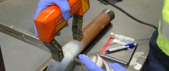
Installing a vacuum frame
It is also a vacuum chamber (“suction cup”). It is a rectangular, triangular, round or square metal frame. There is a transparent viewing screen made of polycarbonate (plexiglass) on the top side. An elastic profile made of porous rubber is glued to the bottom, along the perimeter of the frame, the task of which is to ensure a tight and airtight fit to the surface of the OK. In general, the seal is one of the most problematic areas of the vacuum frame. The contact surface is constantly subject to mechanical, temperature and chemical influences. Because of this, the profile becomes tanned over time, breaks, peels off from the body, and does not hold a vacuum. In search of a solution, some manufacturers have switched to silicone and polyurethane seals. The intake-exhaust mechanism - vacuum valve handles (valves) or a three-way ball valve - is responsible for letting in the atmosphere (pumping out air). You can monitor the pressure using the built-in pressure gauge. The handles must be strong enough - during the vacuum process the frame has to be pressed against the surface. Modern models also provide LED illumination of the viewing window (although some members of the Defectoscopist.ru forum have learned to make homemade illumination for old vacuum chambers). It is powered by a built-in battery and makes it easy to detect leaks in the work area. In good lighting, the backlight may not be useful, but when working inside closed “barrels,” for example, it can be a great help. Vacuum frames are available for flat surfaces, as well as for inspection of corner welds, curved objects (pipelines, vessels) and even for overlap welds. Width varies from 65 to 80 mm, length – up to 630 mm. The diameter of round vacuum frames is from 240 to 260 mm. In the case of corner frames for morning seams, they can be designed for installation on external or internal corners. When moving the chamber from one area to another, it is important to ensure that the vacuum chamber overlaps the previously checked area by at least 50–100 mm.
Creating a vacuum inside the frame
The task is to make sure that the air pressure on the back side of the weld is greater than under the vacuum frame. For bubble control of tightness, even a small difference is sufficient. Then air will penetrate through the through defects, “inflating” bubbles in the foam indicator and thereby indicating existing leaks. The now canceled PNAE G-7-019-89 technique required that the pressure in the vacuum chamber be 2.5–30×104 Pa. Regulation RD-25.160.10-KTN-015-15 requires the creation of a vacuum of at least 0.08 MPa. Most modern installations for monitoring tightness using the bubble method comply with this standard with a margin: the operating vacuum for most varies from -0.6 atmospheres to -1.0 atmospheres. Some NTDs talk about evacuation at a pressure drop of 250 mm of water. Art. According to the old “Rules for the technical operation of tanks and instructions for their repair” (1986), the vacuum in the vacuum chamber had to be at least 0.665 MPa for welded joints of steel sheets with a thickness of 4 mm and at least 0.079 MPa for thicknesses greater than 4 mm. A vacuum pump is responsible for creating a vacuum, to which the frame is connected via a quick-release vacuum connector using a hose (for different manufacturers its length reaches 5–13 m). Vacuum pumps are usually equipped with coarse air filters, a pressure control unit, and the most advanced models have the possibility of remote control. The main requirements for vacuum pumps are high air pumping speed, portability (light weight), preferably not too much noise and, most importantly, reliability.
Leak registration
Immediately after applying the indicator liquid, the control area is carefully inspected. When working with soap emulsion, it is recommended to watch for up to 2–3 minutes (in practice, it is often limited to 30–60 seconds). Large defects most often “give themselves away” immediately. When using a polymer composition to detect small leaks, you need to wait up to 10 minutes. The presence of leaks is determined by the appearance of bubbles and rupture of the soap film (if a soap emulsion is used as an indicator liquid) or foam cocoons and the same film ruptures (when working with a polymer composition). If there are no bubbles or swellings, it means that the controlled area has sufficient tightness (just sufficient, not absolute - since such is simply unattainable, the matter is only in the permissible amount of leakage).
Removing tracer fluid residues
Identified leaks are marked with a metal marker or chalk. To avoid corrosive effects on the metal, upon completion of the inspection, remove the remaining soap emulsion from the surface using a broom/brushes/rags. At the end of the shift, the viewing window and the rubber profile of the vacuum frame must also be cleaned of dirt and splashes. To do this, it is better to use mild detergents (or alcohol) and wet wipes.