During various switching processes using electromagnetic starters, relays, contactors and other equipment, the electrical resistance in the switching element changes. In these devices, this function is performed by the gap between the contacts. In the closed state, the resistance becomes very small, and as the contacts open, it begins to increase.
Such changes occur very quickly, in an abrupt manner, and are accompanied by a chain break. In some cases, it is necessary to avoid such a break, so non-contact devices are used in such switching circuits. A typical representative of this group is a thyristor contactor, which includes thyristors that have a nonlinear electrical resistance that can change upward or downward.
Operating principle of a thyristor contactor
The operation of a thyristor contactor is based on contactless switching. This physical phenomenon consists in the changing conductivity of semiconductors connected to the circuit along with the load. During operation, there are no visible breaks in the circuit, and the process itself is as follows: when the circuit is turned off, the conductivity of the semiconductor decreases sharply, and the resistance can reach several tens of megohms. After switching on, the conductivity of the element is restored, and the resistance tends to zero and is measured in milliOhms (mOhm).
Semiconductor devices are various types of triacs, thyristors and transistors, connected in series with the load in an electrical circuit. Their action is based on the phenomenon of electron-hole transition (p-p), providing one-way conductivity from the anode (p) to the cathode (p).
The same principles apply to the operation of a thyristor contactor or AC switch. The most commonly used circuits are those with back-to-back connections of thyristors VS1 and VS2, marked in the figure. Pulses are generated by the control unit when the voltage passes through the zero mark. Under the influence of pulses, the thyristors open one by one, due to their shift between themselves by 180 degrees. As a result, a sinusoidal alternating current begins to move in the circuit. When the instantaneous value of the load current decreases, the thyristors turn off.
Thyristor switches
Thyristors are mainly used for switching AC power circuits.
They are capable of passing large currents with a low voltage drop; they are turned on relatively simply by applying a low-power control pulse to the control electrode. At the same time, their main disadvantage - the difficulty of turning off - does not play a role in alternating current circuits, since the alternating current necessarily passes through zero twice per period, which ensures automatic shutdown of the thyristor. The diagram of a single-phase thyristor switching element is shown in Fig. 9.1.9. Control pulses are generated from the anode voltages of the thyristors. If at the anode of the thyristor VS1
positive half-wave voltage, then when contact
K
, a current pulse controlling thyristor
VS1
through diode
VD1
and resistor
R. As a result, the thyristor
VS1
will turn on, the anode voltage will drop to almost zero, the control signal will disappear, but the thyristor will remain in a conducting state until the end of the half-cycle, until the anode current passes through zero.
In another half-cycle, with the opposite polarity of the network voltage, thyristor VS2 is turned on in a similar way.
As long as contact
K
is closed, the thyristors will automatically turn on one by one, ensuring the passage of current from the source to the load.
Contactors (starters). Thyristor elements (Fig. 9.1.9) are the basis of single-phase and three-phase contactors. In Fig. 9.1.10 shows, as an example, a diagram of a reversing starter for asynchronous motors. The power switching elements are thyristors VS1 - VS10,
which are opened by contacts
K11, K12, K13
of relay
K1
(forward) or contacts
K21, K22, K23
of relay
K2
(backward).
Current transformers TA1
and
TA2
send an overload signal to the
BZ protection unit,
which, acting on the base of the transistor
VT,
removes power from relays
K1
and
K2
and thereby turns off the starter.
Thyristor control stations for asynchronous unregulated electric drives with a power of up to 100 kW of the TSU type are designed in a similar way. The stations perform the operations of starting, stopping, dynamic braking and engine reverse.
The use of thyristors as contactless DC devices is difficult due to the shutdown problem. If in chains
While alternating current thyristors turn on automatically when the current passes through zero, in direct current circuits it is necessary to use special measures to forcibly reduce the thyristor current to zero, i.e., perform the so-called forced switching of the thyristor current. There are many different forced switching schemes. Most of them contain switching capacitors, which at the right moment, with the help of auxiliary thyristors, are introduced into the circuit of the main thyristor and turn on
his.
Rice. 9.1.9. Diagram of a single-phase thyristor switching element
In Fig. Figure 9.1.11 shows one of the forced switching schemes. When a control pulse is applied to the power thyristor VS
the load circuit
R
n is turned on (the current through the thyristor
i
T is equal to the sum of the load currents
i
N and through the capacitor
i
C), the switching capacitor
C
is charged to the source voltage
U.
The polarity of the voltage
c is
indicated in Fig.
9.1.11, a
.
The circuit is ready to turn off, and if at time t
1 a control pulse is applied to the auxiliary thyristor
VSB,
then capacitor C will turn on
Rice. 9.1.10. Irreversible starter circuit
parallel to thyristor VS,
the load current will move from the thyristor
VS
to the capacitor
C
and the thyristor
VS
will turn off.
Under the influence of the source EMF, the capacitor will be recharged. The capacitor voltage ic
will change during recharging from -
U
to
+ U
(Fig. 9.1.11,
b
), and the current
ic
will gradually drop to zero.
Load Rн
will be disconnected from the source.
If now again at time t2
you turn on the load
Rн
, opening the thyristor
VS,
then again the capacitor
C
will be charged to voltage -
U
and the circuit will be ready to turn off again.
Thus, turning off a thyristor on direct current is more difficult than on alternating current. This problem will be finally resolved only after
Rice. 9.1.11. DC thyristor switch circuit ( a
) and a diagram of its work (
b
)
Rice. 9.1.12. Contactless switch diagram Fig. 9.1.13. Oscillogram of short circuit current interruption
creating powerful, fully controllable thyristors, capable of being locked when exposed only to the control circuit.
Automatic switches. Based on thyristor elements (see Fig. 9.1.9), automatic contactless switches of the BA81 series are made for currents up to 1000 A. They are designed to protect electrical installations in networks with a voltage of 380/660 V AC with a frequency of 50 - 60 Hz during overloads and short circuits , as well as for switching with different switching frequencies. These switches use forced switching off of thyristors using a forced switching circuit (Fig.
9.1.12). Main thyristor VS1
series T-160 is controlled by pulses from a high-frequency generator (not shown in the figure).
Thyristor VS1
is turned off by discharging capacitor C through the switching thyristor
VS2.
The latter is turned on from the voltage of the switching capacitor
C
through a low-power thyristor
VS3,
which reduces the power of the control circuit. Capacitor C
charged from the mains voltage through a transformer and diode
VD1.
Each switch consists of three power blocks with back-to-back main thyristors connected in parallel.
Thanks to the use of forced switching of thyristors, protection against short circuits is carried out with current limitation during the shutdown process. In Fig. Figure 9.1.13 shows an oscillogram of short-circuit current shutdown by a thyristor switch. Curve 1
shows the increase in short-circuit current in the absence of protection, and curve 2 shows when the thyristor switch is turned off by a forced switching circuit. As can be seen from the figure, in this case, the increase in short-circuit current is interrupted and the maximum current imax is no more than 0.02 - 0.05 of the short-circuit shock current.
Output devices (intermediate relays). Schemes in Fig. 9.1.9 are widely used as switching devices for control circuits of executive devices (starters, contactors, electromagnets, couplings, etc.). An example is contactless output devices of the UVB-11 type, which are designed to amplify the output command signals of logical devices and switch AC and DC load circuits. They are designed for switching AC circuits up to 6 A and voltage up to 380 V, DC circuits up to 4 A and 220 V.
In Fig. Figure 9.1.14 shows the circuit of the UVB-11-19-3721 amplifier, intended for switching alternating current circuits. VS is used as a switching element
type TS2-25, shunted by varistor
R
for protection.
from overvoltage. The triac is turned on by connecting its control electrode to one of the power terminals using the contact of a reed relay K.
This relay simultaneously provides galvanic isolation of the input and output circuits. Switching off the seimistor
Rice.
Thyristor DC contactors
DC contactors have a number of individual features and characteristics. One of them is the ability to work with much higher switching frequencies during adjustments and conversions of current and voltage. In this they differ markedly from thyristor regulators that provide stabilization in circuits with alternating current. DC devices provide a higher level of performance, and this factor largely determines the scope of their use.
Advantages and disadvantages
The undoubted advantages of thyristor contactors in comparison with conventional devices are as follows:
- With regular switching on and off, there is no electric arc causing destruction of contacts of electromagnetic devices.
- The short response time makes it possible to perform frequent switchings, with virtually no restrictions. Operating modes can be not only long-term, but also short-term.
- There are no moving parts subject to mechanical wear. Therefore, the service life of thyristor contactors is much longer than that of conventional devices.
- Silent operation due to design features.
- Very easy repair and maintenance. Any part of the contactor can be easily replaced within a short time without dismantling the main device.
- If necessary, the thyristor contactor can be easily converted to a different current rating. To do this, install a suitable thyristor with the appropriate technical characteristics.
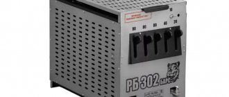
Study of the PT series thyristor starter
The purpose of the work is to study the design, purpose, principle of operation and commissioning of thyristor starters of the PT series.
Work program
1. Study the purpose, general structure and principle of operation of a thyristor starter of the PT type.
2. Test the operation of the thyristor starter under voltage.
3. Check the operation of the thyristor starter protection unit.
3.1. by overheating temperature of thyristors;
3.2. from short circuit current;
3.3. from voltage asymmetry.
Purpose
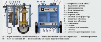
Starters of type PT-16-380-U5, PT-40-380-U5 are designed for remote switching on and off, and reversing starters of type PT-16-380R-U5 are designed for remote switching on and off of three-phase electric motors. Irreversible starters can be used to switch on and off other types of three-phase resistive loads. The starters are intended for use in temperate climate conditions on moving objects and in stationary conditions: in mines, mines, as well as oil, gas, chemical and other industries, provided they are installed in protective shells that meet operating conditions and are included in the power supply circuit individual or group device with a visible circuit break.
Each type of starter has two versions:
Version 1 – for explosive premises;
Version 2 – for general industrial use.
terms of Use
a) climatic influences:
1. ambient temperature from minus 10 to 50ºС;
2. the upper value of relative humidity of the ambient air is 95 ± 3%, at a temperature of 35ºС and lower temperatures without moisture condensation;
3. air pressure within 700 – 1000 mmHg.
b) mechanical influences:
1. vibration in the frequency range from 1 to 60 Hz with acceleration up to 2g;
2. shock overloads with acceleration up to 15g;
3. long tilts in any direction up to 45º.
Starters do not allow operation in aggressive environments containing vapors of acids and alkalis in concentrations that destroy metal and insulation, as well as in environments with conductive dust.
Specifications
The starters are designed to operate in the following modes:
a) long-term, with the number of starts per hour not exceeding 10.
b) repeatedly - short-term, with an on-time of no more than 60%, at a frequency of up to 600 starts per hour with rated load currents.
Basic technical data of PT-16 (40) starters:
Mains voltage – 380 V;
Number of phases – 3;
Mains frequency – 50 Hz;
Rated current – 16 A (40 A);
Electrical insulation resistance – 50 MOhm in a cold state, – 6 MOhm in a heated state.
Average resource is at least 10,000 hours.
The starters have maximum current protection and thermal overload protection. The response time of the thermal overload protection is a function of the overload current and the ambient temperature.
The starters are supplied with protection configured so that the maximum current protection is triggered at 9 - 10 times the rated current, and thermal overload protection is triggered at a temperature on the thyristor body no higher than 105ºС.
Push-button control of starters with and without command fixation. Control from contactless logic elements is possible.
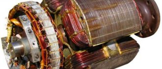
Device and principle of operation.
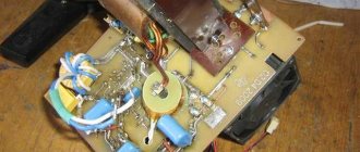
Structurally, the starter is made in the form of a single block. Thyristors are installed on coolers. A temperature sensor is attached to the lower right cooler. At the bottom of the starter there is a control unit, which is attached to the supporting corners with screws and can be tilted to access elements located on the back of the block. Relays in starters of version 1 are placed in containers to protect the relay contacts from mechanical damage and dust. The installation wires are inserted into the container through a gland with a rubber seal.
Starters of version 2 differ from starters of version 1 only in the material of the insulating panels.
The insulation, creepage distance and clearances of version 1 starters comply with the rules for the manufacture of explosion-proof and mining equipment OAA 684 053–67.
The electrical circuit diagrams of the starters are unified and differ only in the number of elements and the type of power thyristors. The starter circuit consists of a power circuit, a control circuit, a protection circuit and a power supply. The power part consists of thyristors connected in each phase counter-parallel.
The principle of operation of the starters is the contactless switching on and off of the load, which is carried out by power thyristors. Power thyristors are controlled by the pulse-width method. Thyristor control pulses are generated from the anode voltage of the thyristors. Let's consider the operation of a starter using the example of one phase of an irreversible starter.
In the initial state, all thyristors are closed and are under phase voltage. After closing the contacts of relay KL1, let us assume that the positive half-wave of the network voltage of thyristor VS1 will flow through the control junction of thyristor VS2, relay contact KL1, resistor R14 and the control junction of thyristor VS1. Thyristor VS1 will open. When the thyristor opens, the control signal is automatically removed, since the voltage drop across the open thyristor does not exceed 1V. When the current passes through zero, the thyristor VS1 closes. Now a positive half-wave of the mains voltage will be applied to the anode of thyristor VS2. The control current will flow from the anode to the cathode of thyristor VS2 through the control junction of thyristor VS1, resistor R14, relay contact KL1 and the control electrode of thyristor VS2. Thyristor VS2 will open and the control signal will be automatically removed from it. Control pulses arrive at the thyristors synchronously with the mains voltage. At the beginning of each positive half-cycle, i.e. via 360 email hail The duration of control pulses depends on the opening time of the thyristors and is automatically set to optimal depending on changes in the load power factor. Thyristor control pulses are generated similarly in other phases. With this method of generating control pulses, the contacts of the switched-on relays are practically in a de-energized state, since a low-current signal passes through them, lasting from tens of microseconds to units of milliseconds during each half-cycle of the current. Therefore, the service life of the relay is determined not by electrical, but by mechanical wear resistance, which for electromagnetic relays reaches tens of millions of cycles.
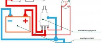
The starter works as follows. When mains voltage is applied to the starter terminals L1, L2, L3, transformer TV receives power. (see circuit diagram).
The rectified voltage from the rectifiers on diodes VD5 - VD6 is supplied to the elements of the protection circuit. The control circuit elements receive voltage from the rectifiers only when the “On” button is pressed.
When the “On” button is closed, relay KL1 or KL2 is turned on, respectively. After turning on the relay, its normally open contacts in the thyristor control circuits close. The thyristors open and the mains voltage is applied to the load.
When the “On” button is released (when the starter is operating without fixing the command) or opening the disabled button (when working with the command being fixed), the relay is turned off, control pulses are removed from the thyristors and the load is turned off.
The protection unit is designed to turn off the starter in emergency modes and keep it in the off state until the load is inspected and the fault is eliminated. Resistor R6 is used to regulate the threshold for thermal overload protection.
Let us consider in detail the operation of the protection unit against various emergency modes.
Overcurrent
By pressing the "Start forward" ("Start reverse") button, a negative potential is supplied from the power source (12) to one end (26) of the KL1 coil ((27) of the KL2 coil), and a positive potential is supplied to the other end (23) through an open collector junction of transistor VT3. The relay is activated and closes its contacts in the control circuits of three thyristor pairs of the corresponding phases. Transistor VT3 is in the open state during normal operation of the thyristor starter, since a negative unlocking voltage is supplied to the base from the power source (12) through the ballast resistor R11 and the bias resistor R12.
With a symmetrical three-phase load and no asymmetry of the supply voltage, the currents in the linear wires L1, L2 and L3 are the same and are shifted in phase by 120°. The secondary windings of current transformers TT1 and TT2 are connected according to a geometric difference circuit and the resulting current, equal to the linear current of any phase, flows through resistor R13, creating a voltage drop across it. This voltage, after rectification by the diode bridge VD14 - VD17, is supplied to potentiometer R5. From its moving contact, part of the negative potential is supplied to the anode VD8, while its value is less than the breakdown voltage of the zener diode, therefore a positive voltage acts on the base of VT1 and the transistor is closed. When the line current in the load increases by more than 20% of the rated value, the voltage on R5 will also increase, which will lead to a breakdown of VD8 and the supply of an unlocking potential through the diode VD7 to the base of VT1. The transistor opens to saturation and the positive potential from its collector through the diode VD1 is supplied to the base VT3 and locks the transistor. The coil of the switched-on relay KL1 (KL2) loses power and opens its contacts in the thyristor control circuits, which leads to their shutdown.
Capacitor C3, shunt potentiometer R5, does not allow short-term surges of current in the linear wires, even when starting the engine, to turn on current protection.
In an asymmetrical operating mode, one of the phase currents may not change, for example IA, in another phase it may even decrease (IC), and in the third it may increase (IB), as shown in Figure 24b. In any case, the geometric current difference IA - IC will increase and if the asymmetry is more than 20%, the protection will operate as described above.
a b
Figure 24 – Vector diagrams of phase currents in:
a) symmetrical, b) asymmetrical load operating modes
Engine overheating
To implement this type of protection, a temperature sensor RD is glued to the motor housing (usually inside the terminal box), which is connected to terminals 2, 3 of the thyristor starter, and its resistance increases with increasing stator temperature.
The second temperature sensor R8 is mounted on one of the thyristor radiators. The thyristors in the circuit are selected with a six-fold current reserve, therefore, at the rated starter currents, the radiators will always be at ambient temperature. This means that protection is provided not against overheating of the stator winding, but against the motor temperature exceeding the ambient temperature. The magnitude of this excess is set by resistor R6.
In the initial state, transistors VT1 and VT2 are closed. An increase in the signal from resistors R6 or R7 to the value of the reference voltages of the zener diodes VD4 and VD8 leads to the unlocking of transistors VT2, and then VT1, as a result of which the emitter-base junction of transistor VT3 is shunted by transistor VT1 through the diode VD1.
Transistor VT3 turns off, which turns off relay KL1 or KL2.
Since transistor VT2 remains open along the circuit point 2 (+) of the protection block, emitter-collector junction of transistor VT1, resistor R2, base-emitter junction of transistor VT2, zener diode VD4, point 4 (-) of the protection block, transistor T3 remains locked until the circuit returns to its original state, for which it is necessary to turn off the mains voltage at the starter input.
Figure 25 — Schematic diagram of the PT-16 thyristor starter