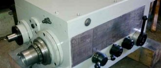
Design features of collet chucks
The design of the clamping chuck includes a clamping nut and a set of collets. The main difference between this type of equipment and quick-release chucks is that in the first case there is no need to use additional devices, which is why the collet chuck is also called self-clamping. Chucks are widely used when equipping lathes due to their simplicity and reliability during operation.
Using a collet chuck, drills, cutters and taps with shanks with a small diameter are fixed. In this case, the tool itself is attached to a replaceable collet, which is also inserted into the chuck and tightened with a nut. In this case, the cartridge is pressed inward, deformed, and the tool is compressed.
Diaphragm cartridge design
To maintain the accuracy of centering of the workpieces being processed, it is advisable to use membrane chucks. Its device is based on the operation of the main element - the membrane. For cartridges of this type, both the internal and external surface of the workpiece can serve as the base for fastening.
Figure 3 shows the fastening of part 1 at the ends of the screws 4, connected to the membrane 2 using horns 3. Bending in the direction of the installed part, the membrane acts on the horns and screws, allowing the workpiece to be installed, after which, by moving the membrane in the opposite direction, the workpiece is firmly attached to cartridge. The screws also serve to further regulate the compression of the workpiece.
Rice. 3. Diaphragm cartridges: a, b – open-end; 1 – workpiece; 2 – membrane; 3 – horns; 4 – screws; c, d – cup-shaped; 1 – membrane; 2 - screw
Types of clamping devices
Based on the type of design, the following types of cartridges are distinguished:
- retractable;
- retractable;
- with fixed collets.
Also, cartridges are classified depending on their purpose:
- The feed cartridge is a bushing made of hardened steel. The design has the form of springy petals formed from three cuts and pressed together at the ends. It is imperative that the shape and dimensions of the cuts correspond to the profile of the rod itself. This type of collet is installed on a special supply pipe by screwing, then the pipe is subjected to so-called axial movement and moves the rod placed in it using cams (in some models, the movement is produced by a hydromechanical drive).
When the equipment is loaded, the bar is “pushed” through the petals of the feed chuck, during this process the petals gradually move apart and, with the force of their elasticity, press the product to the surface of the bar. During the movement of the feed pipe, these petals are compressed under the influence of friction and thus increase adhesion when feeding the bar.
This type of cartridge also has its disadvantages: different shank diameters require the selection of separate collets. But despite this, the use of a feed cartridge is very common.
Most often you can find cartridges with ER type collets.
- The clamping chuck has the form of a steel bushing with springy petals, the number of which is determined depending on the diameter of the part intended for processing. When this parameter is up to 3 mm, a collet with 3 petals is sufficient; if the diameter does not exceed 80 mm, a chuck with 4 petals is suitable, but for products with a diameter exceeding 80 mm, a chuck with 6 petals is used. The apex of the cartridge cone at the corner is 30 degrees. To increase grip, reduce the clearance of the slots while retracting the collet into the chuck.
To fasten parts with a small diameter, split-type clamping collets are chosen, i.e. their cams are moved apart by means of springs. Sometimes the collet may have a replaceable type insert, the shape and dimensions of which are selected depending on the shape and size of the rod.
Characteristics of lathe chuck
The accuracy and quality of processing on a lathe largely depends on the installed chuck. The chuck for a wood lathe secures a workpiece of piece or rod type and transmits the main cutting movement.
Machining at high cutting speeds requires the chuck to have high centering accuracy and reliable workpiece clamping.
Variety
The cartridges differ in design depending on their functional and technological purpose.
Lathe chucks are classified according to several criteria:
- Method of attachment to the machine: on the spindle flange, using an adapter flange, directly on the machine spindle.
- Jaw installation: independent movement, mounted directly on the spindle flange.
- Principle of workpiece securing: manual, mechanized (with hydraulic or pneumatic drive).
The principle of manual workpiece clamping
The use of a mechanized drive reduces the amount of auxiliary time spent on installing and securing the workpiece. The drive ensures precise positioning of the workpiece and centering during installation; this mechanism helps to increase processing accuracy.
Lathe chucks have different numbers of jaws. They can be 2, 3 and 4 cam. The cams are in direct contact with the workpiece during operation and hold it in one position. There are direct and reverse.
The tree (blank) is fixed by the outer surface or hole for parts in the form of bodies of revolution; prismatic parts are attached to the outer edges.
The cartridge is a complex technological product of a prefabricated design. Various materials are used in the manufacture of assembly units. The body is made of gray cast iron grade SCh 30. The material for the parts is tool steel with high tensile strength and heat treatment. Roughness on working surfaces is not higher than 1.6.
Classification
Depending on the design, lathe chucks are:
- lever;
- self-centering;
- wedge;
- collet;
- membrane
Lever view
Perhaps the most popular design. The action of the mechanism is based on the movement of cams and clamps due to the mobility of a two-arm lever. The presence of a hydraulic drive allows you to optimize the design.
The main characteristics of the device include the number of clamps for securing the cam and the ability to move along the working disk. Setting up such a cartridge is quite difficult, especially with non-standard processing.
Changeover occurs according to two schemes:
- Independent adjustment of the cams is a labor-intensive operation and is not performed for every design type of chuck.
- Synchronous movement of cams with a key.
To carry out adjustment, a special key is installed in the groove for adjusting the hydraulic drive.
When working with a device of this type, there is a slight play of the part when rotating. For this reason, lever designs are more often used in roughing.
Self-centering view
The workpiece is centered in the chuck due to the simultaneous movement of the jaws, which is typical for a three-jaw self-centering chuck. Synchronous movement of all cams is ensured by the rotation of the disk, at the end of which grooves are made in an Archimedes spiral.
A bevel gear is cut on the opposite side of the disk. It engages with three small tips. When the key is turned, a small geared bevel gear meshes with the disk is rotated.
The disk begins to rotate and moves the cams inserted into the grooves of the spiral. Changing the direction of rotation brings the cams together or apart from the center. The bringing together or spreading of the cams is accompanied by clamping or squeezing the workpiece.
In power-driven chucks, the clamping force is provided by a hydraulic cylinder or pneumatic cylinder mounted on the rear side of the spindle. The cylinder rod is connected by means of a rod to the mechanism for moving the cams in the chuck. The rod passes through the central hole in the spindle. Moving the piston to one side or the other means that the workpiece is clamped or released.
Wedge view
Structure of the wedge chuck
The wedge design appeared after the improvement of the lever chuck.
The accuracy of movement of each cam was ensured after installing separate mechanical or pneumatic drives, which made it possible to use the device for precise operations.
The wedge chuck has an undeniable advantage over other designs. It has the function of shifting the workpiece axis from the central axis of the machine. The presence of eccentricity expands the machine’s capabilities for processing parts of complex configurations.
Characteristic features when working with wedge chucks:
- Difficulties in setting up for surgery.
- High installation accuracy with a low percentage of error.
- The evenly distributed load from the clamping force by each jaw increases the reliability of securing the workpiece.
A lathe with a CNC device needs quick readjustment. In such machines, clamping modules are installed with the ability to connect to a control system.
The material from which wedge chucks are made must meet high quality standards. The performance characteristics of the chuck must not be allowed to change during high speed machining.
Collet type
Pneumatic collet chuck for lathe
A collet chuck will help you quickly and reliably fasten a cylindrical part on a lathe. During the first installation, difficulties may arise; a specialist should study the instructions, as well as the technical data sheet of the product.
The collet, which is the main structural element, is a bushing with longitudinal axial slots. Due to the slots, elastic clamping petals are formed. They serve as cams when clamping the workpiece. Their number varies from 3 to 6 in accordance with the diameter of the sleeve. The collet is placed in a housing with a clamping nut.
The workpiece installed in the sleeve is evenly compressed by the petals due to the pressure of the nut on the cone, which creates a compressive force. The workpiece receives rigid fixation, and there is almost no radial runout.
The collet-type chuck is designed for a long period of operation, and the number of fastenings and removals is not regulated. The master needs to develop a principle of operation of the machine, with the help of which the efficiency will be optimal. Modern units are easy to customize; many workshops offer installation services for such equipment.
Membrane view
Membrane-type lathe chucks are characterized by high accuracy of centering and securing the workpiece.
A membrane made of elastic material is located on the flange of the mechanism. Clamping jaws with replaceable jaws are installed on it. The number of cams varies from 3 to 8.
When securing the workpiece, the pneumatic drive is turned on.
Pneumatic drive of a lathe
Under pressure, the membrane bends, the jaws diverge by 0.1–0.2 mm. The workpiece is inserted into the chuck until it stops and the drive is turned off. Under the action of elastic forces, the membrane tends to return to its original position. The jaws compress the workpiece.
Such a process takes a small amount of time, but the master requires scrupulousness, attentiveness and caution. The production process should not be taken lightly. Unit parts easily fail under pressure.
The membrane, made of spring steel, firmly holds the workpiece during processing. As the number of cams increases, the centering accuracy increases.
Membrane chucks are used for finishing operations with low cutting forces. The specifics of the work are not known to every master; it is necessary to study the regulatory framework, as well as the recommendations of professionals.
How to choose a part
The optimal chuck model for the machine is selected based on a comprehensive methodology. First of all, the technical data of the machine and the operations performed are taken into account. Based on this, the following parameters are analyzed.
Working diameter – experts pay attention to the outer diameter of the device and the size available for installation on such equipment. The fit size of the groove and the location of the fasteners are important.
Design - the method of securing the workpiece, the location and number of cams are important.
Parameters of the workpiece - you need to know the maximum and minimum diameter of the shaft and hole of the future workpiece, weight, length, configuration. These factors influence the method of fastening - direct or reverse cams.
The size of the hole in the hollow spindle for installing a rod workpiece. As well as the rotation speed range.
The operating conditions of the lathe chuck require placement in a closed room, where the negative impact of natural factors and aggressive environments that can cause corrosion is excluded.
The lathe chuck is an integral part of the lathe and without it machining is impossible.
Related video: Homemade lathe chuck
promzn.ru
Purpose of collet chucks
The main purpose of the collet chuck is to fix the workpiece, this is especially true with a small diameter of the product. If the profile of the part does not fit the shape of the cartridge inlet, additionally use replaceable cartridges from the kit.
Devices designed for automatic longitudinal turning machines have some differences compared to a conventional collet chuck. In this case, it is possible to simultaneously use special collets and conventional chucks.
The advantage of clamping parts using collet chucks is that such a product is perfectly centered. Self-clamping chucks can be operated without keys, unlike quick-release chucks.
Some people confuse milling collets with standard jaw chucks. The difference is that a jaw chuck is used to hold drills of different sizes and diameters, while collet chucks are only suitable for clamping a cutter with a certain shank diameter. Visually, the sets of collets are almost identical, so before use you must make sure that the sizes match. At the same time, it is the collets themselves that differ in diameter, while the sizes of the nuts are the same.
Removing the collet chuck from the nut is quite easy, so one nut can be used with a whole set of chucks.
Self-production
For working on wood, metal and plastics and for making a variety of printed circuit boards, a small drill is best. It should be equipped with a ready-made mini-clamp- type mount. But if you don’t have one at hand, you can easily make it yourself. Here you will need a soldering iron, millimeter-thick steel wire and solder. Next, the manufacturing process proceeds according to the following scheme:
- We roll the wire into a spiral. Its diameter must be equal to the diameter of the electric motor shaft and the drill with which it will be necessary to work;
- Solder the spiral. High quality is ensured by soldering flux or similar options;
- Then we put the spiral on the shaft - and the mini-chuck for our drill is completely ready.
Homemade collet chucks are perfect if there are no ready-made clamps for drills and if you have the appropriate skills to make such mechanisms yourself. They will also become indispensable in the household, when work with specific parts is required, and ready-made clamps may not be suitable for any specifications.
The collet is an important element in lathes of various modifications. With its help, you can carry out work on processing and milling metal and plastic parts. In addition, you can easily make it yourself using available materials . The variety of such mechanisms available today allows you to choose the optimal clamp model for your personal needs. It is also very important to take into account the method of attaching it to the spindle and the dimensions of the flange, since without them it will be impossible to select a collet. Have fun working with different types of clamps!
Collet sets
Chucks with a set of replaceable collets are intended for clamping axial workpieces and cutters on milling, turning, drilling equipment and CNC machines. All collets work on the same principle; the only difference is in the sizes and types of collets.
The market offers a variety of sets of collets from domestic and foreign manufacturers, but all of them are manufactured in accordance with GOST or DIN. Particularly popular are collet sets marked ER, OZ and ER - they can be used for conventional machines and CNC equipment.
In terms of functionality, sets of collet chucks are no different, but the contents may be different. For example, one set may include 18 collets, while another set contains 23 devices. Manufacturing enterprises purchase the kits needed for a specific machine; for a private master, a minimum set will be enough.
Collet for milling machine
A set of collets for milling machines is simply necessary, since this tool simply cannot work without them, due to the impossibility of securing the cutter itself. Collets are often presented as a single structure, but in fact the entire securing structure also consists of nuts and lock washers.
Set of replacement collets for router
This fact alone indicates that it is simply necessary to know all the nuances of the design and operation of collets so that work on milling machines is as simple as possible, more productive and without breakdowns.
General information
Sometimes drill chucks are confused with milling machine collets.
But this is a mistake, since the jaw chuck is used to clamp different diameters and sizes of drills, while collets for milling machines must always correspond to the diameter of the shank of a particular cutter.
That is, simply put, it would be a mistake to assume that a cutter with a shank measuring ½” (12.7 millimeters) will be able to “attach” to collets with a diameter of 12 millimeters, and a cutter with a shank of 6 millimeters can easily be clamped into collets measuring ¼ ” (6.35 millimeters).
This will be impossible, since the size of the collets for milling machines must always correspond to the size of the shank of the cutter with which some kind of docking manipulation is performed.
And, despite the fact that a set of collets for a milling machine are almost identical visually, in fact, it is always necessary to make sure that specific collets (or collets with a nut) are exactly sized for the required router.
Collet chuck and collet set
It is important to understand that in all models of milling cutters, the nuts are usually identical in size, while only the collets themselves differ in working diameter.
The collets can be easily removed from the nut and, if necessary, only one nut can be used with the existing set of collets. However, having a complete set of collets with a nut prepared in advance for work is much more convenient and practical.
How to choose the right collet chuck
The first thing you need to pay attention to when choosing a collet chuck is the type of spindle mount, since the clamp can be attached directly to the spindle itself, screwed onto a thread, or installed through an adapter.
The second condition is the size of the flange (the diameter of the flange for connection or the parameters of the Morse taper) - without having an idea about these parameters, it is impossible to select a cartridge.
Next is the number of cams: sets can include two, four or six pieces. The price of collet sets will vary depending on the number of jaws, their shape and the material used for manufacturing (fasteners can be made of hard metal or soft metal, depending on their purpose).
As mentioned earlier, it is imperative to check that the parameters of the nozzles correspond to the diameter of the shank.
Operating principle
When working with a milling machine, as well as with a drilling or turning machine, there is a need to secure the workpieces while maintaining their position as the required manipulations are performed. A collet chuck is required for this.
Collet chuck for milling machine
Regardless of the type and size, the operating principle of such elements is the same. The pressure on the end of the collet is transmitted from the clamping nut. In turn, this clamp moves towards the cone opening, reducing it. Strong compression and ensures reliable fixation of the element.
If you need to remove a part from a metal milling machine, simply unscrew the specified nut.
When performing manipulations on equipment equipped with a collet chuck, vibrations of the workpiece are minimal - the mandrels securely hold the element. It itself is always well centered, regardless of the type of cartridge.
Fastenings of this kind are relevant for various parts (rods, bushings and others), as well as when performing their secondary fixation on equipment. They always come with a set of cartridges of various sizes, the use of which is used when the profile of the part has a non-standard shape.
Classification by technical device
A typical collet differs from many cartridges in that it can be easily removed and, as noted above, even disassembled in some modifications. But collet devices also differ in the way they are combined with machine equipment. In the same metalworking, static non-removable (fixed) and built-in removable models are used. Also, the collet chuck can be retractable or retractable. Belonging to one group or another is determined by the grip configuration of the processing tool, the range of angles of mechanical action and the control system, since there are manual and, to varying degrees, automated equipment adjustment units.
Design features
Their main components are:
- collet;
- frame;
- screw.
Nut for collet chuck
The housing is designed for installing a clamp on routers. It must be reliable and durable, not allow any mechanical damage or deformation. Therefore, certain alloys are used for its production.
The nut ensures reliable fixation of the part by the chuck, preventing it from oscillating or moving. It is available in several types - self-clamping or quick-clamping (it requires a special key).
The collet itself is a regular sleeve where the back of the cutter fits. As the nut is tightened, the element will be firmly fixed by compressing it evenly. Its diameter varies.
Collet position in the chuck:
- motionless;
- retractable;
- Retractable.
A hole is provided in the feed collet to hold the workpiece tightly. It is usually placed on a rotating rod. If it is necessary to fasten some element with a very small size, a detachable clamping sleeve is used. By means of a special spring inside it, the cams are moved apart.
Clamps, regardless of their design features, are used to secure parts or tools for metal processing on a milling machine. They are selected based on the existing cutter diameter.

