Precision is paramount | 04/14/2018
When cutting threads yourself - internal or external - you often need a thread gauge. It will help you select the correct thread profile parameters and avoid problems with the manufacture of the second part in the connection. Today, we will talk about the types and work with this simple tool.
Device and functionality
A thread gauge is a set of templates made from durable metal plates. Their thickness is about 1 mm. One end of the plates has cutouts with a caliber comparable to the thread being measured - pitch and profile. Masters call such plates with teeth combs. Metric combs have a thread pitch designation, inch combs indicate the number of threads that fit in one inch.
The main functionality of the device is to accurately establish:
- Thread wear.
- Thread pitch.
- Number of threads per unit distance.
- Manufacturing of threads according to GOST.
Before you start working with the device, you need to make sure it is working properly. Damage and deformation must be excluded. The area of the thread being examined is freed from oil and other dirty components. Burrs and defects are eliminated. One comb is selected from the entire mass, which will closely match the profile of the thread being studied. In this case, there should be no gaps. Measurements cannot be taken without a caliper. It determines the diameter of the thread.
What types of devices are there?
What should you pay attention to in order to avoid mistakes when choosing products? The best manufacturers produce two types of popular models:
| View | Description |
| Metric | It is used when working with workpieces that have metric gradations. The device is used to measure the pitch and profile of cutting with a diameter from 1 to 600 mm. The number of plates in the set is 20 pieces. They are toothed combs made of durable steel. Their main function is to find out the cutting coefficient from 0.4 to 7 mm. The correct name for the instrument is a metric instrument. Able to assess the correctness of fastenings (nuts, bolts, studs, etc.). Despite the simplicity of the design, it is quite durable. The corresponding marking “M60” is applied to the body. Included in the list of basic tools in instrument making, mechanical engineering and other similar areas of activity. |
| Inch | Designed to work with inch cuts. An indispensable item in plumbing, aircraft manufacturing, radio electronics, and machine tool manufacturing. Regardless of whether the product is from a domestic or foreign manufacturer, the set contains 17 toothed plates. The angle of location differs from the metric device. The smallest comb has 28 turns. The largest has 4 edges. The pitch is determined based on the number of threads per 1 inch. The body is marked “D55”. Devices are produced for professional and household use. An indispensable assistant when repairing plumbing fixtures at home. |
Which product is best to buy depends on many factors. In addition to the main ones, you can find on sale other variants of popular models:
- Universal. According to buyers, it is the most ideal device for those who are constantly faced with the need to measure threads and determine their condition. The set consists of plates for calibration with metric and inch scales. Designed to work with any type of cutting. Made from durable and wear-resistant material. It is very popular among locksmiths.
- Trapezoidal. The device is designed specifically for working with trapezoidal cuts. They are called “T-thread gauges”.
To make the right choice, you need to know the main difference between a metric and an inch device. The metric tool is designed to determine the distance between turns, while the inch models set the number of turns per 1 inch.
Device characteristics
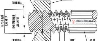
Threads, regardless of whether they are metric or inch, can be external or internal. The main parameters are considered to be:
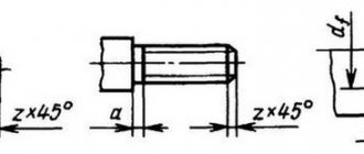
- Depth. Distance between top and bottom.
- Step. Represents the distance between the vertices of adjacent turns.
- Inner diameter. Size of the cylinder with existing coils.
- Outside diameter. Measured at the tops of the coil. Parameter of the workpiece at the cutting site.
- Profile angle. The distance between the side parts of the profile in the axial plane. Measurement is carried out in degrees.
Thread template set
This is a convenient thread measuring tool used to check thread pitch by matching serrated patterns to the profile of the threaded surface on the part.
Inch thread gauges UNC / UNF, BSPP / G show the number of threads per inch, and metric thread gauges show the pitch, that is, the distance between adjacent ridges in millimeters.
A thread pitch gauge consists of a set of plate gauges (templates) pivotally connected in one metal holder. Each plate has serrations in the form of a thread with a corresponding pitch value. As a rule, in one bundle there are probes with a fine pitch, in the other – with a coarse pitch. There are also combined meters, with templates of metric standards on one side and inch standards on the other.
Scope of application
Any bolt requires a nut. To get the perfect kit, you need to correctly determine the diameter of the bolt. We are talking about the external size, which will be the initial value when selecting a connecting element. Some craftsmen use calipers to determine the diameter.
It is not enough to determine the correct diameter. You also need to find out the exact type of thread. It can be either inch or metric. Masters who constantly deal with such details determine everything accurately. The visual differences are pronounced. However, things are more complicated with the thread pitch size. Even a professional mechanic cannot install it accurately. In order not to guess, but to determine the value, you need to resort to the help of a tool.
The cutting step must be set in the following situations:
- To understand whether it is possible to increase the make-up length.
- When carrying out surface treatment of nuts and bolts.
- Establishing the possibility of cutting several turns of cutting.
- Identification of the stability indicator of the connections used, based on operating conditions.
The tool helps determine the type of slicing the user will encounter. The tool is in high demand among professional builders and manufacturers of all kinds of workpieces with threads. This device helps repairmen of various equipment. It makes it possible to determine the build quality.
Combs are a universal thing. They help not only to measure the pitch of the turns, but also to determine their number with the fill level of the profile.
Rules for using the device
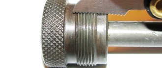
Before determining the thread pitch, measure its diameter. This is a necessary condition, since not all cuts have the full range of steps. This applies most of all to small (up to 5 mm) and large (over 120 mm) cuts. Without a caliper it is impossible to determine the outer diameter. Once the indicator is established, it is worthwhile to figure out the step. In this case, a thread gauge will be an indispensable assistant. The measuring system does not cause any particular difficulties. The rules for using it are as follows:
- The device is picked up and a suitable plate with teeth is selected. It is applied to the threads of a bolt, nut or screw.
- The plate is selected until a complete match is established.
- As soon as the edges of the comb coincide with the cutting on the workpiece, the step value is set.
- The value is indicated on the side of the comb.
It is easiest to measure the external thread. To measure the internal pitch, the measurement area must be illuminated. In the same way, measurements of inch and metric markings on workpieces are carried out. If, when measuring metric cutting, the figure is 1.75 mm, this indicates that the distance between the vertices of the spiral is 1.75 mm. When receiving a value of 28 when cutting in inches, it means that there are 28 turns in one inch.
At the end of the work, the tool must be put in order. This involves cleaning the edges from dirt and dust that may settle during measuring manipulations.
How to choose a device
The choice of any tools, including a thread gauge, should be approached with particular seriousness. Which company is better to purchase products depends on many factors, including personal preferences. Experts recommend being wary of budget options. They may be of poor quality, which can lead to negative consequences in the future.
Everyone's selection criteria are different. Much depends on the scope of use of the devices. Some prefer metric models, while others cannot imagine their activities without inch analogues. The best devices cost a lot of money, but working with them is easy and simple. The material of manufacture is also important. The original devices are made of durable steel. Their accuracy is beyond doubt.
The problem of where to buy structures is not worth it. The shelves of specialized retail outlets are filled with goods from the best manufacturers. New products are released every year, which experts advise you to familiarize yourself with. There are both inexpensive and expensive products.
You can order products online in the online store. It is advisable to first study the list of goods offered, evaluate its quality from photographs, and review reviews. The main thing is not to fall for the tricks of a careless supplier who, instead of expensive popular models, will try to sell a cheap, low-quality Chinese counterfeit.
Safety rules when working with the device
Despite the simplicity of the tool, there are certain rules for its operation that must be strictly followed. The main provisions are as follows:
- The cleanliness of the device must be excellent, regardless of whether it is metric or inch. This will help extend its service life and avoid possible failure.
- To store the device, you need to get a strong and dense container with a hard surface. The ideal option would be a box or container.
- You cannot use other devices that are not intended for carrying out measuring manipulations instead.
- The workpiece with the markings made must be firmly fixed and in a stationary position. If this is not done, a significant measurement error may occur.
- The master, regardless of experience and skills, must wear special clothing to avoid the possibility of injury.
- It is strictly forbidden to operate a faulty product. The probes should be smooth, no scratches, chips or dents. The presence of defects will negatively affect the accuracy of the measured data and subsequent calculations.
It is worth noting that many problems arise due to the poor quality of the materials used in the manufacture of products. Long service life is guaranteed for steel structures. If you purchased an inexpensive product with a body made of plastic, expect it to fail prematurely. Plastic is not particularly durable, so with regular active use of the device, it can quickly fail.
Rating of high-quality and inexpensive thread gauges
This practical and relatively inexpensive set of custom templates is a favorite among experienced professionals. With its help, a person can easily determine whether the thread matches the diameter. The range is calculated using millimeter measurements. Useful both at home and in professional workshops. Product weight 0.025 kg. Dimensions declared by the manufacturer are 75x15x15 mm. The error factor is 15 microns. The set consists of 17 different templates.
- high quality of assembly and consumables;
- excellent equipment;
- time-tested brand;
- packaging that can be used for further storage;
- service life.
Source
Types of thread gauges and features of determining the thread pitch on bolts and nuts
When cutting threads on workpieces, it becomes necessary to use not only taps and dies, but also a thread gauge. This tool allows you to identify thread profile parameters, eliminating future difficulties with the manufacture of second elements in the connection. The device evaluates the accuracy of the cutting performed, so craftsmen whose field of activity is related to the manufacture of threaded parts simply need to have a thread gauge. What types of thread gauges there are, and how the thread pitch is determined using this tool, you will learn about this in detail in the material.
What is a thread gauge and its purpose?
First, let's find out what a thread is. A thread is a spiral that has a constant pitch over its entire area. The spiral is cut using special tools on the surface of cylindrical and conical products. This spiral is also called cutting, through which a detachable connection of parts is ensured. To obtain a spiral on a product, not only the cutting method is used, but also rolling. When working with threads, it is important to have a thread gauge and be able to use it correctly.
The tool in question is similar to feeler gauges for setting thermal gaps between valves on car engines. However, such similarity is manifested only in the external design, and what a thread gauge is remains to be understood in detail. A thread gauge is a small device, the price of which does not exceed 200-300 rubles, consisting of a set of probes with teeth. It is due to the presence of teeth on the plates that this device differs from a feeler gauge for measuring the distance between valves.
Plates with toothed probes are attached to the tool body, and they are made of steel alloys. Each probe is equipped with a unique tooth shape, differing in such parameters as pitch, thickness and direction of rotation. The main purpose of the device is to measure thread pitch on various parts. It is due to this purpose that this instrument belongs to the category of measuring instruments. Moreover, this tool can be used to determine the thread pitch, both external and internal, which is achieved due to the presence of a ground surface.
There is a corresponding marking on the body of the instrument, which is presented as “D55” and “M60”. Few people know what these letters and numbers stand for. However, you need to understand this even before you learn to use a thread gauge. The marking “M60” indicates that this device is intended for measuring metric threads, and “D55” - for identifying inch threads. The digital designation indicates the angle between the vertices, that is, on a metric thread it is 60 degrees, and on an inch thread it is 55 degrees.
A digital designation is also present on the front surface of each toothed comb. The indicated values correspond to a specific thread pitch, which simplifies the identification process. For the manufacture of devices, manufacturers use the following grades of tool steel:
These types of steels are distinguished by such advantages as a low coefficient of thermal expansion, as well as a reduced hardenability index (the ability of steel to accept hardening). It is due to these advantages that thread gauges can be used over a wide temperature range. The production of measuring instruments occurs in compliance with established standards. The production of tools is standardized to GOST 5950-85.
The combs have a special design, which allows, when taking thread measurements, not only to correctly set the pitch, but also the degree of filling of the profile with the determination of the number of threads. It is especially important to determine the number of threads or turns when parts are used that have ground threads with defects present on them in the form of a groove on the grinding wheel.
Thread inspection devices
For comprehensive control and measurement
external metric threads use rigid limit ring gauges (GOST 17763-72 and GOST 17764-72), as well as threaded clamps. Internal threads are controlled using thread plug gauges (GOST 17756-72 and GOST 17759-72). When using threaded plug gauges and rings, the pass gauge acts as a complex meter. A no-go gauge is used to measure the limiting size of the average diameter.
Ring gauge M 1.1x0.25 6h PR for complex control and measurement of external metric threads
During element-by-element inspection
the outer diameter of the bolt is checked with any instruments that are usually used to control the diameter of shafts. And the inner diameter of the nut is used for hole control.
To control the average diameter, contact and non-contact methods are used. The first is based on the use of micrometer inserts or three wires.
Measuring mean diameter with thread micrometer inserts
A thread micrometer with inserts is used to measure the average diameter of a triangular thread with profile angles of 60 and 55 degrees. The measurement is carried out in the range from 0 to 350 mm. For each 25 mm interval, either a separate micrometer or special interchangeable anvils are used.
Threaded micrometer MVM-50 GRIFF with inserts for measuring average diameter
The standard kit includes two inserts: a prismatic one, which is placed instead of the micrometer heel, and a conical one, installed in the hole of the micrometer screw.
The micrometer can be equipped with one of five sets of inserts, which are selected depending on the pitch of the thread being tested: 0.4–0.5; 0.6–0.8; 1–1.5; 1.75–2.5; 3–4.5 mm.
Monitoring the thread pitch and profile angle using indicator measuring instruments
The thread pitch and profile angle are measured using microscopes and projectors. In this case, the average diameter of the internal thread is controlled:
- indicator devices with sliding half-plugs;
- indicator devices with sliding inserts;
- horizontal optimeters using measuring arcs with ball measuring tips.
It is convenient to measure the dimensions of parts during processing using an indicator device. Thanks to the special design of the stop bar, this device allows you to install the indicator holder in a convenient place. The device is universal and can be used both for boring and turning.
Indicator device for active dimensional monitoring during lathe processing
The use of indicators and setting rings with the nominal size of the hole being machined reduces the time for preliminary operations and ensures high accuracy in measuring the internal dimensions of the thread.
When processing holes, the cutter is adjusted according to the indicator to remove the first chip with an allowance of 0.1–0.2 mm per side. After this, the indicator readings are measured, and the first chips are removed. The resulting hole size is measured with an indicator device adjusted to the setting ring with the nominal hole size. When setting up, the indicator device is set to zero.
After measuring the hole, they determine which layer of metal needs to be removed to obtain the final size of the hole. Then, according to the indicator, the cutter is installed under the boring of the finishing hole. This measurement method simplifies boring holes according to accuracy classes 2 and 3.
If the batch of parts is large, it is more convenient to first perform preliminary boring of all products with an allowance of 0.3–0.5 mm per diameter, and then complete the finishing boring in one pass with a rigid cutter. The use of indicator devices allows you to work confidently and with great accuracy. However, the indicator does not eliminate the need to use maximum calibers. Measuring the thread with a gauge is a mandatory procedure that is required for final size control.
What are metric and inch threads
Before you figure out how to determine the thread pitch using a thread gauge, you need to find out how a metric thread differs from an inch thread and vice versa? Threads according to the system of measures are divided into two main types:
- Metric - used on the following types of fasteners: bolts, screws, nuts, studs and others. The metric type of cutting originated in the Soviet Union and is actively used today
- Inch is the American cutting standard that home craftsmen encounter when working with plumbing products. However, inch cutting is found not only on plumbing fixtures, but also on fasteners
Let's look in more detail at the question of how metric threads differ from inch threads, and where they are used most often.
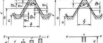
A distinctive feature of metric threads (GOST 24705-91) in the corresponding profile shape, which looks like an equilateral triangle.
The angle between the vertices of this triangle is 60 degrees, as mentioned above. The vertices or peaks are blunt in shape, that is, the projections for mating with the screw or nut are cut off. The unit of measurement used to indicate the screw diameter and thread pitch is millimeters. Threads of this type can have coarse and fine pitch, which depends on the scope of application of the relevant parts. Parts with small pitches are used primarily for adjustment, as well as in devices subject to dynamic loads. To designate large threads, markings in the form of the letter M and the corresponding number are used, for example, 20. This means that a metric thread with a diameter of 20 mm is cut on the workpiece. Small threads on the workpiece have a similar designation, only a digital value is added. This value indicates the thread pitch, for example 1.5 mm. The photo below shows a diagram of a metric thread device.
In addition to metric, inch threads are often used (GOST 6111-52).
Beginners who do not know about the existence of these two types of cutting face some difficulties. To understand what these difficulties are, consider the design features of inch threads. In profile it has a similar shape as the metric one, but its main difference is the modified angle between the vertices. This angle is 55 degrees, which distinguishes it in design from metric cutting. The unit of measurement used to indicate the dimensions of inch threads is inches. There are 25.4 mm in 1 inch, and two strokes are used to indicate inches. Inch thread can also be large or small, and is characterized by the number of threads per inch. It will not work to screw a nut with a metric thread onto a part with an inch thread, and vice versa.
Inch and metric threads are external and internal, and their main technical parameters are:
- Pitch is the distance between the two tops of the turns
- Depth - distance from top to bottom
- Profile angle is the distance in degrees between the side parts of the profile in the plane of the axis
- Outer diameter - the size of the workpiece in the area where the thread is present, measured at the tops of the turns
- The inner diameter is the distance that corresponds to the size of the cylinder with the coils present
When you know the difference between metric threads and inch threads, you can begin to consider the question of how to learn how to use a thread gauge. Although this device has a simple design, not everyone is able to correctly make the appropriate measurements (in addition, many do not know that there is a special tool). The effectiveness of the connection depends on the correctness of the actions performed.
Measuring the average diameter of a thread
To measure the average diameter of a thread, you must use a thread micrometer complete with different tips (one with a cone, the other with a cutout). The measurement limit is usually indicated on the measuring instruments themselves. Thus, the marking M 3–5 means that the kit allows you to measure threads in increments of 3; 3.5; 4; 4.5 and 5 mm.
Inserts for thread micrometer
A micrometer is used to measure the average thread diameter. Replaceable tool tips are inserted into the screw hole and allow for the most accurate measurements.
If averaged values are sufficient as a result, calipers can be used instead of a micrometer. By design, it consists of ball tips, the dimensions of which must match the type and pitch of the threaded connection. To find out the average diameter, the tips of the calipers must be aligned with the thread gauge. Then the procedure is repeated with the sides of the part. Threaded clamps are used to evaluate measurement results. And the accuracy of the diameter is checked by comparing the resulting thread with the template.
To control the average diameter of a thread consisting of a maximum of two turns, use the two-wire method. The measurement is carried out as follows: wires, the diameter of which coincides with one of the tabular units, are placed on the opposite protrusions and recesses of the thread. In this case, the distance between the ends of the wires shows the average diameter of the part. For each accuracy class, separate wires are created that comply with GOST 2475-88. When deriving final numbers, possible errors are taken into account, because the two-delay method does not allow achieving accurate values.
Another method for measuring the average thread diameter is to use a microscope. The device is applied to the side of the workpiece profile, and the eyepieces are pointed at the profile image on each side to determine its size. The values obtained as a result of measurements are added and divided by the number of sides. The resulting arithmetic mean is the average diameter of the threaded connection.
How to distinguish metric threads from inch threads
Only craftsmen who deal with threads on a daily basis are able to distinguish metric from inch threads, or vice versa, by eye. If a non-professional tries to distinguish threads by eye, there is a very high risk of mistaking a 5/16-inch UNC bolt for a metric M8. You can determine compliance with the thread type using a thread gauge, but when such an identifier is not available, you must resort to other methods.
The easiest way to understand what type of thread is on a bolt is to use a nut with already known parameters (and vice versa). If this is not possible, then you should resort to the following actions:
- Inspect the head of the part, which may have radial lines
- If radial lines are present on the head of the fastener, this indicates the presence of an inch thread.
- The absence of radial lines confirms the use of metric threads
However, this method is not always acceptable, since fasteners with strength classes from 0 to 2 are not marked. The presence of lines and numbers on the bolt head indicates the strength of the product.
Why do we need thread gauges?
To equip a bolt or other part with a nut, such an important parameter as the diameter is taken into account. This is the outer diameter of the part, according to which the element for connection is selected. You can find out the diameter of the thread (internal or external) on the workpiece using a caliper. When choosing a connection element, you also need to know the type of thread - metric or inch. However, this does not pose any difficulties for craftsmen who are faced with such details. Above is a detailed description of how metric threads differ from inch threads. You can distinguish them visually, but what to do when you need to find out the thread pitch? Even the most experienced mechanic cannot determine it, so thread gauges are used specifically to find out the value of this parameter.
The need to determine the cutting pitch arises in the following cases:
- If you need to perform surface treatment on a bolt or nut
- To clarify the possibility of increasing the make-up length
- To determine the resistance of a threaded connection to operating conditions
- To determine the possibility of cutting one or more threads
Using a thread gauge, you can also determine the type of thread the user will be working with. The use of this tool is in demand only among craftsmen who manufacture various products and workpieces with threads, as well as specialists involved in the repair of various equipment.
Measuring the internal diameter of a thread
The internal thread is measured using calipers. The tool is installed on a template part using a thread gauge, and then compared with the original internal diameter of the threaded connection. To obtain accurate values, the caliper must be positioned at an angle to the axis being measured.
You can also use cylindrical thread gauges to measure the internal diameter of a thread. This is because the inner diameter has a smooth surface and is ideal for the shape of the tips used in these instruments. The results obtained are checked using plug gauges.
Types of thread gauges and their features
Due to the fact that there are two main types of threads - inch and metric, it is not difficult to guess that the tools for determining them are of two types:
- Metric - designed exclusively for working with workpieces with metric threads. The device measures the pitch and profile of cutting, the diameter of which ranges from 1 to 600 millimeters. The design of the tool contains up to 20 combs, which are steel plates with teeth. Using these plates, you can determine the cutting pitch from 0.4 to 7 mm. Such a device is called a metric thread gauge, since it is used to determine the pitch and profile of the metric thread already existing on the workpiece. The devices allow you to evaluate the correct manufacturing of fasteners such as nuts, bolts, studs, etc. Metric instruments are distinguished by their simple manufacturing design, high strength, and corresponding markings on the body in the form of “M60”. The scope of application of the tool is mechanical engineering, instrument making, etc.
- Inch - designed only for working with inch types of cuts. The device is used in the field of radio electronics, aircraft manufacturing, plumbing, as well as in the production of various machine tools. The set of inch thread gauge contains 17 plates with corresponding teeth, which differ from the metric device in angle of location. The smallest comb has 28 turns, and the largest has 4 edges. The pitch is determined by the number of threads per 1 inch. A distinctive feature of the inch tool is that there is a marking in the form “D55” on the body. In the household, inch thread gauges are used when working with plumbing fixtures
- Trapezoidal - a special device designed to work with trapezoidal types of cuts. Another name for this device is T-thread gauge
- Universal - devices that have plates for calibrating inch and metric threads. Such devices allow you to simultaneously work with different types of cuts, which is especially important in plumbing
When you know what types of thread gauges there are, it remains to understand the issue of their correct use. If you don’t know how to use a thread gauge, then we’ll look at the procedure for determining the thread pitch in detail.
Thread measuring instruments. Thread measuring wires.
Active control devices.
One of the most progressive control methods is active.
Its most rational use is in conditions of mass and large-scale production. Active control devices for a certain dimensional measurement allow you to automatically change the course of the technological process and ensure the specified processing accuracy. Active control devices can be turned on at the end of the processing cycle and, based on the measurement results, issue a command for sub-adjustment of the cutting tool (they are called sub-adjusters) or check the dimensions of the product directly during processing in order to regulate the amount of movement, cutting modes and other parameters of the technological process. Active control devices that regulate the parameters of technological processes are used in computer-controlled machines.
For automatic control and adjustment, contact and non-contact devices are used. For contact action devices, the tip is in contact with the product being measured and can, when triggered, cause an error in the device. To reduce this possibility, the tips of active monitoring devices are made of carbide, diamonds, agates or other particularly hard materials.
Devices for measuring threads.
The main controlling parameters of threads are the outer middle and inner diameters, profile angle and pitch. When measuring threads, complex and element-by-element control means are used.
For comprehensive control of external metric threads, rigid limit ring gauges ( GOST 17763 - 72 and GOST 17764 - 72 ) or threaded clamps are used. Internal threads are checked with thread plug gauges ( GOST 17756 - 72 and GOST 17759 - 72 ). When using threaded plug gauges and rings, the complex meter is the pass gauge. A no-go gauge is used to measure the maximum size of the average diameter.
With element-by-element inspection, the outer diameter of the bolt can be checked by any measuring instrument used to control the diameter of shafts, and the internal diameter of the nut by any measuring instrument used to control holes.
To control the average diameter, contact or non-contact methods are used. The contact control method is based on the use of micrometer inserts or three wires.
Thread micrometer inserts.
A micrometer with inserts is used to control the average diameter of triangular threads with profile angles of 60 and 55°. The measurement is made in the range from 0 to 350 mm, and for each 25 mm interval either separate micrometers or special interchangeable anvils are used. The set of inserts for the micrometer consists of two inserts (Fig. 1): a prismatic one, which is installed instead of the heel of the micrometer, and a conical one, installed in the hole of the micrometer screw.
Rice. 1. Inserts for thread micrometer.
The micrometer is equipped with five sets of inserts, which are installed in relation to the pitch of the thread being tested: 0.4 - 0.5; 0.6 - 0.8; 1 - 1.5; 1.75 - 2.5 and 3 - 4.5 mm.
Measuring threads using the three-wire method.
When checking the average diameter, a set of three wires of the same diameter is used. During the measurement process, two wires are installed in the thread recesses on one side, and the third in the opposite recess. The size of the wires is selected according to a special table depending on the pitch and angle of the thread profile. The ideal size for wires is the diameter d = tan α /2c, where cs is the pitch, and α /2 is the profile angle of the thread being tested.
Measuring the average thread diameter.
Depending on the required accuracy when measuring with wires, micrometers or optical-mechanical devices are used, which provide more accurate readings. If the axes of the wires are located vertically during measurement, then the wires are suspended on a bracket mounted on the device used (Fig. 2). Measuring surfaces are brought to the wires and the distance between the protruding points of the three wires located in the recesses of the thread is measured, then the average diameter is determined using the formulas.
Calculation of the average thread diameter.
Medium thread diameter with profile angle 60°:
Dcp = M – 3 d + 0.866 s ,
where M is the size obtained as a result of measurement, mm;
d—wire diameter, mm;
s — pitch of the measured thread, mm.
If the profile angle is 55°, then the average diameter of the cylindrical thread:
Dcp = M – 3.165 d + 0.9605 s .
Rice. 2. Measuring the thread using three wires.
Non-contact methods of thread inspection using the average thread diameter are based on three wires, the use of measuring microscopes with goniometric eyepiece heads, and also projectors.
Indicating measuring instruments.
Monitoring the accuracy of the thread pitch and measuring the profile angle is also carried out using measuring microscopes or projectors.
Control of the average diameter of the internal thread can be carried out with indicator instruments with sliding half-plugs, indicator instruments with sliding inserts, as well as on horizontal optimeters using measuring arcs for internal measurement equipped with ball measuring tips.
At most factories, when boring holes for preliminary measurements, they use plugs and punches, as well as calipers. Installation of the cutter to remove chips to the required size is carried out along the dial of the machine's transverse support based on the readings of the caliper. When machining holes according to the 2nd and 3rd accuracy classes, this generally accepted measurement method is associated with a large amount of time spent on removing test chips, and often on unnecessary passes.
You can measure the dimensions of a number of parts during processing using an indicator device (Fig. 3), which, thanks to the special design of the stop bar 1, allows you to install indicator holder 3 4 in a convenient place, in front of the transverse slide of the caliper. When feeding the transverse slide away from you, the indicator pin rests against the protrusion of bar 1. Screw 2 protects the indicator from breakage. This device is universal; it can be used both for boring and turning. For turning, the stop bar and indicator 3 are rotated 180°.
Rice. 3. Indicating device for active control of dimensions during machining on a lathe.
Practice has shown that the use of indicators and setting rings with the nominal size of the hole being machined, as well as the use of an indicator device (Fig. 3), can reduce auxiliary time and ensure high accuracy of measurements of internal dimensions.
When processing holes, it is necessary to use the indicator to adjust the cutter to remove the first chip with an allowance of 0.1 - 0.2 mm per side, note the indicator reading and remove the first chip. After this, measure the resulting hole size with an indicator device adjusted to the setting ring that has the nominal size of the hole (when adjusting, the indicator device is set to zero).
Having measured the hole, it is determined which layer of metal needs to be removed with a cutter to obtain the final size of the hole, and using the indicator, the cutter for boring the hole is set to the finishing size. This method of measurement simplifies boring holes according to the 2nd and 3rd accuracy classes, and it is quite accessible to low-skilled workers.
For large batches of parts of small mass, it is sometimes advisable to first carry out preliminary boring of the entire batch of parts with an allowance of 0.3 - 0.5 mm per diameter and then, in one pass, using a rigid cutter, carry out finishing boring.
Considering that the cutter wears out during operation, as a result of which the size of the hole decreases, during the processing of each subsequent part, you should check the actual size of the hole of the already processed part with an indicator for internal measurements and, based on the indicator readings, adjust the indicator device taking into account the wear of the cutter.
The advantage of working with an indicator is that its readings are not affected by wear on the threads of the screw and the nut of the transverse caliper, whereas the readings on the dial depend on the degree of thread wear.
It should be noted that generally accepted methods of boring holes do not provide high accuracy. When processing a hole whose diameter is smaller than the specified one, the turner does not have an exact idea of how many hundredths of a millimeter need to be additionally removed to obtain the final size. Therefore, he is often forced to resort to additional passes, which significantly increases processing time and degrades quality.
The use of indicator devices makes it possible to work confidently and with great accuracy. The use of an indicator does not exclude the use of limiting calibers. Checking the holes with the limit gauge is mandatory during the final size control.
How to use a thread gauge correctly - step-by-step instructions
Before determining the thread pitch, you must first measure its diameter. This is done because not all cutting diameters can have a full range of pitches. This is true for small cuts less than 5 mm, as well as for large ones - over 120 mm. To determine the outer diameter of the thread, you will need to use a caliper. After determining the diameter, you can begin to measure the thread pitch. A thread gauge is used for this. If there is no device, then there is another way to determine the thread pitch, which many people still use today. Detailed instructions on how to use a thread gauge are as follows:
- On the device, you need to select a suitable plate with teeth, and attach it to the threads on the nut, screw or bolt
- The selection of plates to the cutting shape is carried out until a complete and exact match is achieved
- When the edges of the comb coincide with the cutting on the workpiece, the step size is determined
- The value is indicated on the side of the comb
This completes the process of determining the thread pitch. The easiest way to measure is the external thread. If the pitch of the internal thread is measured, then it is necessary to additionally highlight the location of the measurement. In a similar way, measurements of metric and inch threads on workpieces are carried out. If metric cutting measurements are taken, then we obtain the corresponding value, for example, 1.75 mm. This means that the distance between the vertices of the spiral is 1.75 mm. If measurements are taken of inch cutting, then we get a value, for example, 28. This means that there are 28 turns in one inch.
More details about how to use a thread gauge are described in the video clip.
Measuring thread pitch without a thread gauge
Parts with external thread
Often the need to determine the thread pitch arises sporadically, at one time. And, of course, in such a situation there is no thread gauge at hand, and it makes no sense to buy one for one-time measurements. It will be useful to learn how to measure the thread pitch with a ruler or caliper. These measuring tools make it quite easy to determine the desired parameter.
The easiest way is to measure the threads of a bolt or other externally threaded part. When measuring a metric thread, it is recommended that you first attach the ruler to the threaded part and try to align the millimeter divisions of its scale with the tops of the ridges of the threaded profile. If they coincide, then the step is 1 mm. Otherwise, you will have to carry out slightly more complex measurements.
To determine the thread pitch, you need to count the number of turns on a section of a rod of a certain length, for example, 10 mm or 20 mm. To obtain a more accurate result, it is recommended to take measurements on a 20 mm area. The required length is measured by applying a ruler to the bolt shaft, or using a caliper. It would be more accurate to measure the bolt thread pitch with a caliper. In the measured area, count the number of turns. After this, the length of the section must be divided by the resulting number of turns minus one turn. As a result, we obtain the value of the thread pitch.
When determining the pitch of an inch cutting, it is necessary to measure the length of the rod equal to one inch (25.4 mm). For accurate measurements, it is better to use a ruler or caliper with an inch scale. The number of turns in this area will be the thread pitch. If the length of the threaded section is less than one inch, then you need to determine the number of turns in a section of half an inch (12.7 mm), and then multiply the result by 2.
Internally threaded parts
There are two ways to measure the thread of a nut or other internally threaded part without a thread gauge. The first method involves selecting an exactly suitable counter bolt and then measuring its thread pitch. If you can’t find the counter bolt, then you need to use a strip of paper (this is method No. 2).
It should be pressed against the thread so that an imprint of the profile remains on the paper. You can improve the visibility of marks by tracing the edges with a marker. After this, on paper you need to mark the distance between the extreme marks with a ruler and count the number of turns. Then the resulting distance is divided by the number of turns minus one turn. Instead of measuring paper using this method, you can use a pencil, match or other soft wood product of a suitable size, which is pressed against the thread.
Instructions for determining the pitch of a trapezoidal thread
In addition to metric and inch threads, there are also trapezoidal threads. It differs from the types discussed above in that its profile has an angle of 30 degrees. This type of cutting is used mainly in the design of mechanisms where rotational energy is converted into translational movements. The most striking example where trapezoidal threads are used is a vice.
To designate this type of cutting, the marking Tr is used, and the cutting pitch is measured in millimeters. If on metric cutting the pitch is the distance between the vertices, then on trapezoidal cutting it is the same distance between the teeth. Below in the photo the letter P indicates the pitch of the trapezoidal thread.
To measure it, there is a special T-thread gauge, which is more expensive than inch and metric instruments. In order not to buy it if it is necessary to determine the pitch of a trapezoidal thread, there is a corresponding algorithm. To do this, you need to measure the outer diameter and compare it with the table values, obtaining the corresponding result.
Thread gauge-ruler
Our store offers unique and easy-to-use tools for quickly sizing fasteners. They are made either in the form of a template ruler or a square and are designed to measure the length, diameter and thread pitch of nuts, washers, bolts and screws in inch (American) and metric units. Durable plastic/metal and compact size allow you to carry the fastener gauges in your pocket and store them wherever you need them.
- Simply place your bolt against the templates and read the length.
- Use gauge holes to quickly determine diameter.
- Measure the inch and metric thread pitches by placing the bolts against the thread templates and placing the nuts on the gauges.
The template ruler will be useful to sales assistants in stores that sell fasteners and, ultimately, will help consumers make the right choice regarding the bolt they are trying to use to replace a failed one. A measuring tool for bolts and nuts will be an excellent gift for any craftsman working in the field of maintenance and repair of cars, household appliances, electronics, and equipment.
Metric and inch bolt templates are made to order in the USA, as evidenced by the inscription on one side of the ruler.
Recommendations for working with thread gauges
When using thread gauges, you need to take into account some features. These features look like this:
- It is recommended to store the device in sealed boxes or containers to prevent mechanical stress and deformation of the instrument.
- High-precision measurement results can be obtained using only a special tool, and you should resort to using a ruler, caliper and micrometer in exceptional cases when there is no specialized device at hand
- When identifying threads, it is necessary to ensure that the workpiece remains stationary. Otherwise, this will negatively affect the quality of the measurements taken.
- Thread gauges have sharp edges, so it is important to observe safety precautions during operation
- If there are external defects on the probes of the device, then such an instrument cannot be used for making accurate measurements. Defects in the form of scratches, chips, dents, etc. will negatively affect the accuracy of the calculations performed.
On sale you can find not only metal, but also plastic thread gauges. As a rule, the body is made of plastic, and the probes are made exclusively from special grades of steel. Devices with a plastic body have a significant drawback - low strength, but at the same time they cost no more than 100 rubles.
In conclusion, it should be summarized and noted that determining the thread pitch of bolts, nuts and other fasteners is not particularly difficult if you know the algorithm and own a special tool. The obtained values after using a thread gauge allow the production of a second fastener to ensure a strong and removable connection.
Source