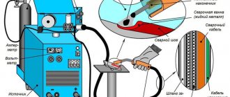
Purpose and device
The development board for solderless assembly allows you to mount an electrical circuit and run it without using a soldering iron. In this case, you can check all the parameters and characteristics of the future device by connecting measuring and control devices to the board.
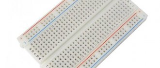
A breadboard is a plate made of a polymer material that is a dielectric. Mounting holes are drilled on the plate in a certain order, into which the leads of the parts - components of the future device - should be inserted.
The holes allow the connection of leads with a diameter of 0.4-0.7 mm. They are located on the board, as a rule, with a pitch of 2.54 mm.
To simulate the connections of the component leads to each other, the breadboard has special conductive plates that connect the holes in a certain order.
Typically, these connections are made in groups along the board along its long sides. There may be two or three such rows. These contact groups are used as buses for connecting power.
Between the longitudinal rows, the holes are connected by plates in groups of five. These plates are located in a direction across the board.
Near the holes in the places of future contacts, the current-conducting plates have design features that allow them to clamp and firmly hold the leads of the parts, while ensuring the presence of electrical contact. This is the meaning of installation without soldering.
Quality prototyping boards can be assembled and disassembled while maintaining a strong and reliable connection between parts up to 50,000 times.
Breadboards produced industrially and purchased in a retail chain, as a rule, have a layout of contacts and conductive connections between the holes.
How to use it correctly
In order to successfully and efficiently use the breadboard, you must also have the following devices:
- several mounting wires with a diameter of 0.4-0.7 mm for installing various jumpers and connecting power;
- side cutters;
- pliers;
- tweezers.
Of course, a soldering iron is not needed for installation without soldering, but it may be needed to solder wires to the power supply terminals if detachable products are not available. Sometimes soldering will have to be used to implement shielding.
Knowing the location of the conductive paths on the breadboard, it is easy to install any circuit and, by connecting it to a power source, check its functionality. To assemble, you only need to insert the component leads into the connector clamps and connect them in the required sequence.
In this case, it is necessary to clearly understand the location of the conductive paths in order to prevent a short circuit. If it is necessary to make contacts between tracks on the breadboard, connectors are used.
If the diameter of the pins of the parts does not fit the mounting holes, you can solder or wind pieces of suitable wire to them. Chips and components in BAG packages are installed in the center of the board.
Main types of development boards for Arduino and its circuits
Development boards differ in the number of pins located on the panel, the number of buses and configuration. There are boards in which contact connections are made by soldering, but working with them is more difficult than with solderless devices and we will look at them in another article.
Large development board
Colored breadboards
Breadboard with markings
Depending on the characteristics, the most common types are:
- For assembling large chips, solderless boards with 830 or 400 holes are mainly used. For connecting several components and supplying wires to the necessary points - 8, 10, 16 holes;
- With the presence of grooves for adhesion of boards, which allow the implementation of fairly large projects;
- With self-adhesive on the base for secure fastening to the device;
- With symbols printed on the board for connecting devices.
Depending on the cost and manufacturer, the package may also include additional accessories - jumper wires, various connectors. But the main quality criterion always remains the number of contact connectors and their technical characteristics.
To know how to use a development board, you need to understand the principle of its design. It's quite simple.
Development board diagram
The development board has a plastic base with many holes (the standard distance between them is 2.54 mm). Inside the structure are rows of metal plates. Each plate has clips that are hidden in the plastic part of the unit.
The wires are inserted into these clips. When a conductor is connected to one of the individual holes, the contact is simultaneously connected to all other contacts of the separate row. Therefore, by connecting the contacts of other devices to the remaining clips, we connect them with a conductor - a rail with clips.
It is worth noting that one rail contains 5 clips. This is a common standard for all development boards. That is, up to five elements can be connected to each rail, and they will be interconnected.
It should be noted that although there are ten holes in each row, they are still divided into two isolated parts, five in each. Between them there is a rail without pins. This design is necessary to isolate the plates from each other, and allows you to simply connect chips made in DIP packages.
It will be interesting➡ Installation diagrams and methods of connecting solar panels
Connecting the chip to the breadboard
To make it easier to navigate, the breadboard also contains numerical and alphabetic symbols that can be used as a guide when creating, for example, wiring instructions.
Some development boards also include two power lines on each side. Typically, the “red line” is used to supply “+” voltage, the “blue” line for “-”. Due to the presence of two power rails, two different voltage levels can be supplied to the board.
Attention! It is absolutely unacceptable to use breadboards with a voltage of 220V!
If the board is large, then the power lines “break” in the middle. This allows for more connection options. For example, you can assemble devices with 3 and 5 Volt power on one board.
Using the breadboard is quite simple. When creating a circuit, the necessary elements are inserted into the holes on the plastic case - capacitors, resistors, various indicators, LEDs, etc. The width of the connectors allows you to connect conductors with a cross-section from 0.4 to 0.7 mm to the contacts.
Connection diagram of the LED to the circuit board
For example, you need to connect two elements together - an LED and a resistor. To do this, you take the leg of the first element (LED) and insert it, for example, into row number 2. You insert the second leg into another row. For example, 3. If you insert a leg in the same row, the circuit will not work, because both legs will be connected through a common rail by an iron conductor. There will be a short circuit. The current will flow through the connection directly, bypassing the LED. There will be no benefit from this.
Connecting an LED to a breadboard. We place the LED in a convenient place. The main thing is that for each leg there is its own row
If you insert a contact into an adjacent row, there will be no short circuit between them, because adjacent rows are not interconnected by conductors (after all, only 5 contacts in one row are connected). It doesn’t matter which row you stick the leg into. The main thing is that it is not the same as the first leg.
For convenience, in real schemes the second leg is placed not in the adjacent row, but in any other, a little further from the first. You need to choose the installation location taking into account the size of the LED itself, so as not to bend the contacts too much.
So, we have secured the LED - it stands steadily with both legs in rows 2 and 3. Let's now connect a resistor to this circuit. We will take one resistor leg and insert it in the same row as one of the LED legs. For example, in row number 3 - anywhere. There are 5 contacts in one row, it doesn’t matter which contact we end up in, the main thing is that it’s in the same row! Then we insert the second leg of the resistor into another row, for example, into the seventh.
Connecting an LED and resistor to a breadboard. We connect one legs of the elements
It turns out that the legs in the 3rd row will meet each other through the internal connection and will be connected, as if we had soldered or twisted them. And current will flow between them with pleasure, because he loves metal connections.
We have one leg left for the LED and one leg for the resistor. We must connect the LED leg to the Arduino board. If it is a long leg, then we connect it to pin 13. If it is short, then with the GND pin. In our case, we will connect the short leg in the second row to the GND connector on the Arduino board. To do this, we take the male-male wire and stick it in the row where our free leg is located. For us this is row 2 (the second leg of the LED is already connected in row 3 to a resistor). Again, it doesn’t matter where exactly we plug the wire, the main thing is that in the second row – in the one where the LED leg is already waiting. We connect the second part of the wire to the Arduino board.
An example of connecting an LED and a resistor to a breadboard. Let's go to GND
It will be interesting➡ How to calculate cable cross-sections by power and current: formulas and examples
We connect the rest of the circuit in the same way - we lead the second part of the resistor through a conductor to another Arduino connector. In our case, from row 7 we pull the conductor to pin 13 of the Arduino. It turns out that the long leg of the LED goes to the plus - to pin 13. And our short one has long been connected to ground - GND.
That's it, the diagram is assembled. And after turning on the power, the current will go like this (schematically): through the source inside the Arduino it will reach pin 13, through the red conductor it will reach the breadboard, pass through the resistance, then through the LED, then through the black wire it will return to the Arduino. The circuit ended up working without any breaks.
Build and test this diagram. If suddenly something doesn’t work, check the contacts - wires and breadboards from Chinese online stores are not always of impeccable quality.
Another example of creating a circuit prototype using a breadboard could be the following implementation option:
To assemble it you need to take:
- Breadboard;
- wires for connection;
- 1 LED;
- tact button;
- resistor with a nominal resistance of 330 Ohms;
- 9V Krona battery.
The plus of the battery is connected to the positive bus, and the minus to the negative. If the circuit is assembled correctly, then when you press the button the LED will light up.
A few more examples:
Example circuit with breadboard
Example circuit with breadboard
Homemade breadboards
I still found these times at the radio circle. Back then we made breadboards ourselves. We took a sharp cutter and cut squares on foil PCB. Next, they were coated with solder.
If we needed to connect tracks somewhere, we simply made jumpers between the squares with a drop of solder. It turned out high quality and beautiful. If you were too lazy to solder the radio elements onto a normally wired board with tracks, you simply left it as is and used the device.
Disposable development boards
Manufacturers still “fucked up” on this matter, or as they say in economics, demand creates supply. Ready-made mock-up scarves, single-sided and even double-sided, began to appear for every size and taste.
By the way, you can find a whole set of them on Ali.
The holes are very conveniently matched to the sizes of the pins of the microcircuits, as well as other radio elements. Therefore, it is very convenient to assemble and test electronic devices on such breadboards. Yes, and they are inexpensive.
The reverse side of such development boards with ready-made devices will look something like this:
What are the disadvantages of these development boards? It is still better to use them once, since with repeated use their spots may fly off, which will lead to its unsuitability.
Assembling simple circuits on a breadboard
Let's try connecting a few elements and make sure everything works. To assemble these simple circuits we will use the elements:
| Name | Connection feature | What function does it perform? | Picture |
| LEDs | it is a polar element, it has + and - (or anode and cathode) | Burns beautifully | |
| Resistors | for our experiment you will need a resistor from 300 to 1000 Ohms | Limits current to prevent LED from burning out | |
| Tact button | With two or four contacts | Closes and opens a circuit | |
| Battery compartment | With two AA batteries of 1.5 volts each | Powers the circuit | |
| Arduino Nano board | Plugs into breadboard | A controller that allows us to program electronic circuits |
Let's make the LED light up
Rice. 1 Schematic diagram. Assembling a circuit with an LED First, let's draw the circuit that we are trying to assemble. The meaning of the circuit is this: electric current passes through the LED and it lights up, while a resistor limits the current so that the LED does not burn out.
Our version of assembly on a breadboard.
Rice. 2 An example of assembling a circuit on a breadboard.
Please note that it is convenient to connect power to horizontal rows, making them common + and -. These designations on some breadboards are just a hint for you, so it’s convenient to connect. Indeed, it is often convenient to have a common “bus” - a common wire with a plus and a minus. But this does not mean that you cannot connect something else there.
It will be interesting➡ PWM pwm controller: principle of operation, scope, characteristics
Circuit with two LEDs connected in series and a button.
Let’s complicate our circuit a little; now we’ll light two LEDs through a button. The button will allow us to close and open the circuit and thus control the inclusion of LEDs.
Rice. 3 Schematic diagram for exercise 2. Connecting two LEDs in series.
Try to assemble this circuit yourself. Below is our solution.
Rice. 4. Assembling a circuit with two LEDs on a breadboard.
conclusions
Breadboard development boards are optimal for creating prototypes and digital circuits of low complexity. In their practice, they are often used by both beginners who understand the basics of circuit design and experienced professionals due to the ease of installation and the fairly high quality of connecting working contacts. With the help of such boards, you can quickly and without unnecessary soldering create a prototype, test it, and then assemble a device with a more reliable connection option.
Despite the large number of advantages, breadboards also have disadvantages. They do not allow making a reliable device that can be used in difficult conditions. They are not intended for assembling analog circuits with high sensitivity to resistance values, because The resistance at the point of contact depends on many factors and can vary. The boards must not be connected to a high voltage line. Finally, such boards also cost money - circuit boards with soldering are cheaper.
In any case, for the first projects the Arduino engineer does not have any alternatives. In addition, connecting a breadboard promotes the development of abstract thinking - and this is never superfluous.
Rate this article:
Tips for working with soldered boards
Some useful tips to help you assemble the board correctly:
- Immediately cut the board to the required size. For this, ordinary scissors, a cutter, or a hacksaw are suitable. You can even just break it along the holes, but then clean the edges.
- If you are not going to use the board right now, then do not touch the areas with foil with your hands again. Hands may be wet, which will lead to surface corrosion and poor contact.
- If oxides or dirt occur, clean them with fine sandpaper or a regular eraser.
- Radio elements are installed on the side where there are no foil strips. The leads are inserted into the holes and soldered on the reverse side.
- The blue color of the conductive paths indicates the “minus” of the circuit, the red “plus”, and green is used at your discretion. The tracks are marked on the same side where the foil is located.
- The most important positioning of parts occurs in a vertical position, since in this case an error will lead to an incorrectly assembled chain.
Please note that both types of breadboards may have slots on the sides. This is necessary for those who assemble a large device consisting of several modules. The grooves allow you to assemble one large board from several small ones.
The first damn thing is lumpy or immediately troubleshooting
There is an anecdote: a man bought an airplane and a magazine with a description of “How to make a loop.” Following the instructions, I boarded the plane, took off, started doing a loop - everything worked out. He turns the page, and there: “... read the way out of the dead loop in the next issue.”
We can talk a lot about the culture of soldering and the fact that it is an entire art. One thing will remain unchanged: if you do something for the first time and according to a book, then at first it may not work. Here is our first board, the “Chameleon” set, or rather what came out of it. What mistakes were made?
1. The soldering technology is broken, as a result - unsoldered contacts, which are better to be desoldered and soldered again (without mixing up the polarity!) 2. The operating technology is broken: each part was soldered in turn. Below you will see how much more profitable in this regard it is to listen to the instructions and first assemble all the parts, and then fasten them.
Result:
the parts fit beautifully together, but out of three diode chains, only one lit up in the end.
Possible Solution:
Unsolder all the parts and solder them again.
Positive point:
can always be found. In this case, we don’t have “parasitic bridges” anywhere. True, removing them is quite simple in any case: just hold the soldering iron tip and separate the contacts that are soldered together.