Turret lathe 1341
Turret lathe 1341 belongs to the turning group equipment. Using a turret lathe with a set of tools allows you to perform a range of works:
- grooving of external and internal surfaces, grooves;
- drilling;
- processing with a countersink to obtain precise dimensions and ledges;
- when using reamers, obtain a high-quality surface;
- knurling;
- thread cutting;
- processing of shaped surfaces.
They are used in the manufacture of parts with a large number of technological process operations.
Safety precautions
Before working with equipment, you must undergo a medical examination. Operational and safety training is also required. It includes the following rules:
- Do only the work that is assigned to you, and only in a safe manner.
- Work only on equipment in which you have special skills.
- Work only in a special uniform, which is issued before starting work.
- The employee must be provided with ample space to work.
- Before work, it is necessary to check the serviceability of the device.
- Under no circumstances should you attempt to repair the device yourself. Do not touch the internal mechanism of the machine
- There should be no unnecessary items in the workplace.
- The workpiece must be firmly fixed.
- Do not touch the material being processed.
- Do not touch workpieces during operation.
Design Features
The difference between the 1341 turret lathe and universal type lathes is the absence of a tailstock and a lead screw. This is compensated by the presence of a caliper and a head with a turret arrangement of the tool. The head is used by placing a set of cutting tools in its sockets.
Fastening their various types in each of the sockets is possible using specific multi-tool holders. Adjustment (using a holder) ensures that the size specified in the drawing is obtained.
The type of machines includes turret heads with an axis of rotation:
The vertical axis of the head requires additional installation of a transverse support.
Adjustment of the tool stroke is provided by adjustable cams, which automatically switch off the feed. The presence of replaceable tools reduces processing time.
Multi-spindle machines
This equipment is divided into two types:
- parallel action;
- sequential action.
The camshaft is a characteristic part in semi-automatic and automatic lathes. Cams of various shapes and designs are mounted on it (depending on the purpose). They control all auxiliary and working movements of machine tools through a system of mechanical and other connections.
The most commonly used cam designs are:
- drums They are designed to control auxiliary and working movements of machine tools. It is a cylinder that is equipped with overhead cams or shaped milled grooves;
- disk. They are needed to set the working parts of semi-automatic and automatic machines in motion - calipers and turrets.
Discs with end-mounted cams are used only to activate auxiliary movements (rotation of the turret, clamping and movement of the rod, etc.). The discs have a separate scale. Most often it is divided into hundredths of revolutions. This scale is necessary to install the cams in the right place.
Components of model 1341
On the 1341 turret lathe, parts are processed in automatic and semi-automatic modes. Semi-automatic mode is used when processing piece workpieces. They are secured manually with three chuck jaws. In automatic mode, a steel rod is used, fixed with a collet-type chuck. The rod is secured by a hydraulic device.
Kinematic diagram of turret lathe 1341
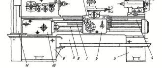
The most important components of the 1341 machine include:
- lower and auxiliary beds;
- boxes: speeds;
- innings;
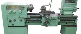
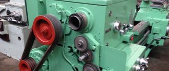
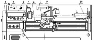
Appearance of machine 1341
Hydraulic cylinder for clamping machines 1G340, 1G340P
Clamping and feeding of bars, as well as clamping of piece workpieces in lathes 1G340, 1G340P is carried out by a hydraulic clamping cylinder (see position 7 in the diagram below). The clamping hydraulic cylinder assembly (in the description of the operation of the machines is designated as the clamping and material supply mechanism 15.10.000) is included in the delivery set of machines 1G340, 1G340P (attached separately in the general packaging). The material (rod) clamping mechanism is discussed below:
The clamping and material feeding mechanism is designed for clamping and feeding bar material, as well as for clamping piece workpieces in a three-jaw chuck. The design of the mechanism, including fixed and movable clamping collets, ensures high position stability (within 0.1 mm) of the end of the clamped rod. The body of the collet chuck 12 is fixed to the front flange of the spindle. The movable clamping collet 15 is connected to the body by driving pins 14. The clamping collet is screwed onto the clamp pipe 9. In the bore of the stationary collet 17, replaceable liners 19 are attached with screws 18, which are kept from turning by pins 16. When moving the clamping collet 15 forward, the material is released; back - clamp. The force on the clamping collet is transmitted by the clamp pipe 9, connected by means of nuts 3 and 4 to the piston 6 of the clamp cylinder 7. Oil is supplied to both cavities of the hydraulic cylinder using a movable oil supply sleeve 8 located inside the spindle head. To clamp parts in a three-jaw chuck, the body of the collet chuck 12, collets 15 and 17, sleeve 21, as well as the feed pipe with the collet are removed.
Settings
The machine is set up by starting a series of identical parts. It provides:
- development: part manufacturing technology;
- setup cards;
- spindle speed;
Some features of the machines
The units described above are characterized by a fairly high level of performance. If we compare them with the most primitive turning installations, this is explained by a number of factors.
- The use of fast devices for feeding and hardening of workpieces.
- Combinatorial operation of the turret and transverse support.
- Quickly change the device used in the work.
- The use of new holders, as well as various tools that differ in their combined appearance.
To ensure high performance and proper functioning, you need to configure it correctly. Proper setting refers to the selection of tools that are used in the work and their installation in holders, as well as the manufacture and installation of a longitudinal or transverse stop. The stop will be adjusted in the axial or radial direction.
On many turret machines, the frequency, as well as the feed and rotation, will be selected using a command device. Chuck units that were produced in Russia or even in the Soviet Union can work with workpieces with a cross-sectional size from 15 to 60 cm. Rod equipment is characterized by the following parameters: the distance through which the head can move is maximally large, the cross-section of the products is small.
Simple turret machines are used in many domestic enterprises. In recent years, you can notice a tendency to exchange them for the most advanced equipment, which has numerical control. CNC machines have many advantages, they are characterized by a high level of automation and operation, as well as good processing accuracy.
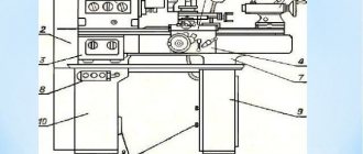
Basic elements of beds
The following is fixed to the main or lower frame:
- cast trough for coolant;
- auxiliary frame with guides for placing and moving the caliper;
- gearbox with spindle;
- gearbox;
- electrical cabinet;
- thread cutting device;
- copying device:
- container for oil used by the hydraulic drive;
- spindle and pump electric motors;
- box for collecting shavings.
General view of the turret lathe 1341
A carbon ruler is mounted on a bracket on the auxiliary frame. The folding stop is located on the right side of the caliper. It is designed to shut off the supply. Its transition to the working or neutral position is carried out using the handle.
Main design features
A universal screw-cutting lathe consists of main structural units, which are standard elements. These include:
- caliper;
- bed;
- thrust and spindle headstock;
- electrical equipment;
- drive shaft;
- guitar gears;
- a box that provides selection and change of feeds;
- lead screw - it is this detail that distinguishes a screw-cutting lathe from a standard lathe.
Depending on some features, the accuracy of the machine may vary. Therefore, universal equipment can be of both accuracy class N and increased – P.
Front and rear stock
The headstock or spindle has the main role of fixing the workpiece in processing and transmitting rotation to the workpiece from the electric motor.
The spindle is located inside the body of the headstock. A speed control handle is mounted on the outside of the machine body. The tailstock or thrust is necessary to fix the workpiece.
Caliper
The support is designed to move the tool holder with the cutter in the longitudinal, transverse direction relative to the axis of the machine. The lower part of the support is called the slide or carriage.
After a certain time of operation of the machine, the support will need to be adjusted, since otherwise the processing speed will decrease. Adjustment for gaps consists of tightening the wedge strip.
Compared to other parts, the caliper is large. The choice of tool holder is determined by the class of the machine. For large equipment, be sure to secure the cutters with an additional four screws.
Gearbox
This is the main part of the spindle drive. It transmits engine energy to the rest of the machine. Another function is to change the spindle speed and the operating speed of the entire machine.
The box is built into the spindle head housing or in a separate housing block. The speed can be changed in a stepless or stepwise manner. The standard gearbox includes the following components:
- gear system;
- V-belt transmission;
- reversible electric motor;
- electromagnetic clutch with braking system;
- handle for changing gears.
The gearbox operates using gears.
Spindle
This is the main part of the machine, which is made in the form of a shaft with a conical hole for securing workpieces. To ensure that the part has high strength and durability, it is made of high-strength steel.
In the classic version, the spindle is made on high-precision rolling bearings. A special ring is installed on the support of the part, which ensures the accuracy of the machine.
There is a conical hole at the end of the structure. The spindle needs a cavity to install a rod that helps, if necessary, knock the center out of the seat.
The strength and durability of the spindle directly depends on the bearings available there.
bed
This is the main part of the machine, which is made using cast iron. All the most important parts and elements of this design are attached to it.
The frame itself consists of two steel beams. The beams, in turn, are connected to each other by stiffening ribs. Each beam has a connection to two guides.
The guides on both sides belong to the prismatic group. The flat-shaped guide is located inside on the left side.
Threading
There are several ways to cut threads using a screw-cutting lathe. For this, a die, tap, cutter and other types of tools are used.
With their help it is possible to cut internal and external threads
When using a cutter, it is important to fully comply with the technology. It includes:
- correct sharpening of the cutter;
- accurate adjustment of machine operating modes;
- using a template, correct installation of the cutter in the center of the part;
- measuring the resulting dimensions using gauges or templates.
In such work, defects in the form of sharp points, torn threads, scuffing and crushing are unacceptable.
Electrical control unit
The standard control unit for a screw-cutting lathe includes several handles and buttons:
- handle for setting the number of revolutions;
- control system for setting cutting surface parameters;
- handles for caliper control.
A CNC machine has a more complex structure, but can work without operator participation at intermediate stages.
Apron
In the apron of a screw-cutting lathe there are mechanisms that convert the rotational movement of the lead screw and the lead shaft into the translational movement of the caliper.
Caliper
The caliper moves along the guides of the auxiliary frame using a rack and pinion.
The support contains:
- turret;
- command apparatus;
- stop drum;
- apron.
The head is attached to a shaft located on the caliper. The shaft rotates on ball bearings. The tool is secured into the head holes using holders. The holders provide rigidity of fastening, accuracy of installation and adjustment of the tool.
The same shaft is used to attach the command device and the stop drum. The head rotates after each working stroke, feeding the next tool to the processing zone. The command device ensures automatic activation of the required spindle speed and feed values corresponding to this type of tool.
Behind the command device there is a stop drum, which ensures automatic stop of the caliper when the required amount of tool movement is reached. The feed is switched off by cams installed in the grooves of the drum when they reach the folding stop.
Turret lathe 1341
Through the action of the cams, the activation of the specified electromagnetic clutches in the gearboxes and feeds is ensured. This allows you to obtain the spindle speed and feed values specified for this operation.
Electrical equipment
The electrical equipment of the 1516 is demonstrated with electric motors, controls and safety switches.
We dismantle the sewerage system in the apartment
Power supply circuit for the 1516 machine
To operate the machine and control it, currents with a wide variety of voltages are used. Thus, the voltage in the general power supply network is 380 V. The coils on magnetic starters use a voltage of 110 V electric current. The clutches located in the speed and feed boxes, as well as local lighting, are clearly 24 V. The step finder uses voltages of 36 and 90 V.
Description of the electrical circuit of the machine 1516. It is equipped with motors whose rotors are squirrel-cage and carry out: the main movement on the machine, the supply of tools, as well as the crossbar and lubrication system.
The electrical circuit for controlling the drives is provided in the photo. The control equipment is located in the niche of the frame. The machine is controlled using a remote control.
Wiring diagram of machine drives 1516
Spindle assembly
Spindle speed and feed rates are adjusted for control modes:
- Automatic - a command device that is configured in advance to perform the technological process. Its design allows you to give a control impulse to the electromagnetic clutches used to switch gears (located in the gearbox).
- Manual - using the toggle switches located on this box.
The spindle unit provides feeding/fastening of the rod using a hydraulic device using a collet.
Clamping/unfastening of bar stock is carried out automatically, piece workpiece is done manually. The part obtained from the bar is cut off, and the turret is returned to the starting position to adjust the length of the other part along the stop.
Lathe repair cost
| Type of work | Price |
| Spindle Prevention | 9,000 rub. |
| Troubleshooting clamping devices | 19,000 rub. |
| Burnout (damage) of the stator winding | 30,000 rub. |
| Replacing bearings with rotor balancing | 50,000 rub. |
| Replacing spindle sensors | 10,000 rub. |
| Maintenance | 10,000 rub. |
| Non-standard work | 10,000 rub. |
| Major renovation | 50,000 rub. |
| Modernization of machine tools | 30,000 rub. |
Our main specialization is machine repair
If your machine does not work, our specialist will arrive as soon as possible and fix it. Call and consult by phone: 8
Technologies
Thanks to the use of modern devices, we can more accurately identify faults. And we save your money on repairs
Ideas
If your machine does not break down as usual. We will send it to our technicians and they will solve any problem
Speed.
You need the machine to work as quickly as possible. Our desires coincide.
Read useful information:
Repair of guide machines
What is the design of machine guides, their features and repair specifics. Service and self-repair.
Further
Machine repair cost
Any equipment with insufficient care and untimely diagnosis fails. In this article, the reader can find information about the types of machines, common breakdowns, as well as the actions of a specialist during repairs.
Further
Machine head repair
The headstock is an important element of the machine. If this part fails, it is very difficult to cope with the repair yourself and you have to contact specialized workshops
How to prevent breakdowns, what is important to know when doing your own repairs and how much the services of qualified craftsmen cost - all this can be found in the article
Further
Repair of metalworking machines
Further
Self-repair of the machine shaft and care for it
In the modern world, the use of complex equipment is associated with wear and tear. In particular, the shafts of various machines are subject to enormous loads due to the large volume of work, and sometimes due to the conditions in which they are operated. The article discusses the main causes of breakdowns, as well as methods of prevention and maintenance of equipment. Questions about repairs for various damage to machine shafts are also covered.
Further
When concluding a long-term service agreement, you receive a discount of up to 20%. Don't forget, we have a guarantee on all types of work.
- engineer - mechanic
- CNC programmer
- Service engineer
- Electrician
- Electronics engineer
- Locksmith - repairman
Copy
The 1341 turret lathe has mechanisms used for thread cutting and copying.
They use a thread cutting mechanism on a copier thread blank using a thread comb. This technology involves multiple passes to obtain a complete thread profile. The device is located in the gearbox housing. Its drive is driven by gears from the spindle.
Another copier has a copying ruler, which is used for longitudinal and transverse copying. In this case, conical and shaped surfaces are obtained. Shaped surfaces are obtained by installing a curved template instead of a carbon ruler.
In the longitudinal direction of copying, the support moves to the spindle assembly, and the turret rotates, repeating the profile of the copier.
Principle of operation
In mass production, the rod is mounted in a collet chuck using hydraulics. There is a built-in mechanism that ensures that the workpiece is fed to the required length. When working with piece workpieces, the turner secures them manually.
Typically, machines are equipped with a universal collet with replaceable jaws for clamping a circle and a polyhedron. The kit includes additional mandrels, bushings and other accessories.
Important!
On some models, it is possible to replace the collet with a three-jaw chuck.
Modifications of machines for chuck work are designed for processing cast, stamped and forged piece workpieces. They are equipped with three-jaw (or four-jaw) chucks.
All tools are mounted in the turret. Having completed the working stroke with one cutter (drill, reamer), it changes position and feeds a new tool. The length of the tool's working stroke is limited by special stops that shut off the feed.
Equipment technical parameters
The dimensions of parts manufactured on the 1341 machine are determined by its parameters. These include dimensions (mm):
- workpieces: when using a cartridge – 400;
- above the caliper – 380;
- round – 40;
The dimensions of the machine are 3.0 * 1.2 * 1.6 m. Its weight is 2200 kg.
Electrical diagram of turret lathe 1341
The electric motor that rotates the spindle has a power of 5.5 kW. The number of speeds used by the machine is 8 (from 60 to 2000 rpm). In addition, there are electric motors:
- hydraulic drive for clamping and advancing the rod (1.1 kW);
- cooling pump (0.125 kW).
Technical characteristics of the machine 1P420PF40
| Parameter name | 1P426DF3 | 1P420PF40 |
| Basic machine parameters | ||
| The largest diameter of the workpiece above the bed, mm | 500 | 450 |
| Largest diameter of the workpiece, mm | 250 | 200 |
| Maximum length of the workpiece, mm | 130 | |
| Diameter of clamping chucks, mm | 250; 315 | 200 |
| The largest diameter of the processed rod, mm | 65 | 50 |
| Spindle hole diameter, mm | 92 | 70 |
| Distance from the end of the spindle to the edge of the turret, mm | 350..850 | – |
| Distance from the spindle axis to the base of the machine, mm | 1120 | |
| The largest size of threads cut with dies and taps, mm | ||
| Number of tools in turret | 12 | |
| Largest cross-section of cutters in the turret head, mm | 25 x 25 | |
| Diameter of the hole in the turret for a cylindrical shank, mm | 40 | |
| Spindle | ||
| Limits of spindle speed with chuck, rpm | 30..1800 | 20..4000 |
| Limits of the speed of the driven tool, rpm | – | 20..2500;20..1500 |
| Number of spindle speeds, rpm | 18 | B/s |
| The end of the spindle is flanged according to GOST 12595-72 | 8 | 6 |
| Maximum permissible torque on the spindle, not less than, Nm (kg*m) | 500 | |
| Maximum permissible torque on the tool spindle, not less than, Nm (kg*m) | – | 10 |
| Caliper. Submissions | ||
| Maximum movement of the turret support: longitudinal (Z) / transverse (X), mm | 560/ 340 | 630/ 240 |
| Speed range of longitudinal feeds of the turret caliper (Z), mm/min | 1..6000 | 1..5000 |
| Speed range of transverse feeds of the turret support (X), mm/min | 0,5..3000 | 1..5000 |
| Speed of fast movements of the caliper along the Z/X axis, m/min | 15 | 10 |
| Speed range of spindle circular feeds (C axis), deg/min | – | 1..2000 |
| Maximum feed force of the turret support along the Z/X axis, kN | 20/ 10 | |
| Turning time of the round turret head, s | 2 | |
| Hexagonal turret rotation time, s | 3 | – |
| The amount of movement of the turret caliper along the Z/X axis per pulse, mm | 0,010/ 0,005 | 0,001/ 0,0005 |
| Discreteness of setting the circular movement of the spindle, degrees | – | 0,001 |
| Number of tools in turret | 8; 6 | 12 |
| The largest diameter of the driven tool, mm | – | 12 |
| Caliper positioning accuracy in the longitudinal direction (Z axis), mm | 0,025 | |
| Caliper positioning accuracy in the transverse direction (X-axis), mm | 0,010 | |
| Spindle positioning accuracy (C axis), min | – | 2 |
| Maximum movement of the quill, mm | 180 | |
| Electrical equipment of the machine | ||
| Number of electric motors on the machine (with electric pumps), kW | 6 | 12 |
| Main drive electric motor, kW | 18,5 | 30/ 22 |
| Electric motor for longitudinal feed drive (Z axis), N*m | 13 | 13/13 |
| Cross feed drive electric motor (X axis), N*m | 13 | 10/13 |
| Circular feed drive electric motor (C axis), N*m | – | 10/13 |
| Drive tool electric motor, N*m | – | 10/13 |
| Electric motor drive of the gearbox lubrication system, kW | 0,55 | |
| Hydraulic pump electric motor, kW | 2,2 | 2,2 |
| Hydraulic station fan electric motor, kW | – | 0,12 |
| Cooling pump electric motor, kW | 0,12 | 2 x 0.12 |
| Main propulsion engine cooling electric motor, kW | – | 0,25 |
| Electric motor for fencing screen drive, kW | – | 0,18 |
| Electric drive motor for chip conveyor, kW | – | 0,55 |
| Total power of all electric motors, kW | 40,54/ 33,54 | |
| Dimensions and weight of the machine | ||
| Overall dimensions of the machine (length, width, height), mm | 3525 x 1570 x 2655 | 3470 x 2260 x 2300 |
| Machine weight, kg | 8660 | 5900 |
Bibliography:
Grachev L.N. Design and adjustment of computer-controlled machines and robotic complexes, 1986, p. 17
Boguslavsky B.L. Semi-automatic turning machines, automatic machines and automatic lines, 1961
Volkevich L.I., Kuznetsov M.M., Usov B.A. Automatic machines and automatic lines, 1976
Zazersky E.I., Mitrofanov N.G., Sakhnovsky A.G. Handbook for a young operator of automatic and semi-automatic lathes, 1987
Itin A.M., Rodichev Yu.Ya. Setup and operation of multi-spindle semi-automatic lathes, 1977
Kamyshny N.I., Starodubov V.S. Design and adjustment of automatic and semi-automatic lathes, 1975
Lisova A.I. Construction, adjustment and operation of metalworking machines and automatic lines, 1971
Pozhitkov A.Ya., Safro I.D. Setting up single-spindle automatic lathes. Reference manual, 1978
Pronikov A.S. Metal-cutting machines and automatic machines, 1981
Feshchenko V.N. Processing on turret lathes, 1989
Fomin S.F. Construction and adjustment of turret lathes, 1976
Related Links. Additional Information
Home About the company News Articles Price list Contacts Reference information Download passport Interesting video KPO woodworking machines Manufacturers
Documentation for the machine
The manufacturer of the turret lathe 1341 is the Berdichev machine tool. The equipment is supplied with technical documentation. One of the fundamental documents is the passport, which is a guide for the turners and mechanics who operate it.
Download the passport (operating instructions) of the turret cutting machine 1341
The passport provides for reflection of the following points:
- requirements for packaging and transportation;
- purpose and principle of operation of the machine;
- operational and technical characteristics;
- compliance with the requirements during commissioning;
- Availability of specifications: for machine control;
- bearings;
- electrical equipment;
- hydraulic mechanisms;
Operating principle of a lathe
The workpiece is secured in a chuck mounted on a spindle. The resulting spindle rotation comes from the main motion electric motor via a V-belt drive.
The tool performs only linear movements in the longitudinal or transverse direction.
A cone installed in the tailstock quill supports a long workpiece or to keep it from bending under high loads during turning. The axial tool that processes the holes is also fixed in the tailstock.
The 1a616 lathe, the operating instructions and passport of which can be found on the Internet in the public domain, in addition to turning, drilling and boring, can perform the following operations:
- shaped turning;
- corrugation;
- running in;
- deployment;
- countersinking.
You can work on the machine with tools made of high-speed steels and prefabricated cutters with carbide plates.
Kinematics
The kinematic diagram of the machine allows for the following types of movements:
- Main movement: n dv · i pp · iv = n sp → n sp. The gearbox is adjusted based on the condition: iv = n sp / n dv · i pp.
- Feed movement: S pr = n dv · i pp · i s. The feed box is adjusted based on the condition: is = S pr/ n dv · i pp.
- Screw-cutting movement: t nr = t xv · i pr · i cm · i pp. Adjustment: i pr = t nr = i cm / (t xv · i pp), where:
- i pr - gear ratio of gear wheels from the spindle to the replacement wheel assembly, i pr = 48/68·34/36·36/48;
- i pp - gear ratio of the gearbox;
- i cm is the gear ratio of the replacement wheels.
Electrics
Electrical equipment on the 1a616 machine is similar to 1b61. These are electric motors, fuses, switches, relays, transformers and local lighting. The power supply and circuit diagram are presented in the passport for the machine.
At the time when the machine was mass-produced, it was equipped not only in workshops and workshops at enterprises, but also in rural workshops. In remote areas, the voltage in the electrical network was 220 V. Therefore, PS8S motors operating on direct current were installed on model 1a616k machines. They provided smooth braking without excessive heating.
The lighting of the working area is organized through a step-down transformer and is 36 V.
Operation and repair
Documents for the machine contain instructions for safe operation, maintenance and repair periods, and lubrication intervals. Installation standards and foundation requirements are also displayed.
Indoor operating parameters:
- humidity - 80%;
- temperature - 10°C - 30°C;
- type of production - serial, piece.
For long-term operation, the recommended overhaul cycle is 5 years (with two shifts). The overhaul cycle includes the following regulations: inspection - 10, minor repairs - 5, medium repairs - 2. The list of work performed can be found in the machine passport.
Models, descriptions, characteristics and types of machines
There is a wide variety of models and types of machines , in this catalog we will try to collect the most popular of them, both on the domestic market and abroad, and write the most complete, detailed characteristics and descriptions of the machines. Add as much technical information as possible, as well as technical documentation for these machines. If you have interesting descriptions of machines or passports for them and you want to share them with everyone, send the material by email, it will definitely appear on the pages of the portal.
We do not post materials with a copyright icon or a prohibition on copying, this is prohibited by law!
Operating principle of turret lathe 1341
The workpiece is mounted in the spindle using a device and performs a rotational movement B1 with a cutting speed vcut.
Tools, pre-installed in the appropriate devices, are mounted in the sockets of the turret head and sequentially come into operation when the turret head is rotated (indexed), making movements of the longitudinal Фs1(П2) or transverse Фs2 (В2) feed in accordance with the technological process of processing the part.
The dimensions of the part in the longitudinal or transverse direction are obtained automatically due to the fact that the size of the path of movement of each tool is limited by the stop that is preset for the processing size corresponding to this tool. Setting the cutting modes in which a particular tool operates is also carried out automatically due to the fact that the cams located on the command apparatus drum, corresponding to each position of the turret head, act on electrical switches that control the inclusion of the corresponding spindle rotation speeds and feed rates (electric switches activate appropriate combinations of electromagnetic clutches in the gearbox and feed box to obtain specified spindle speeds and longitudinal or transverse feed rates).
If the part was processed from a piece workpiece, then after complete processing it is removed from the machine manually, a new workpiece is installed, and the processing cycle is repeated.
If a rod is used as a workpiece, then after complete processing the part is cut off, the turret head is turned to the initial position (a stop for the workpiece is installed in the turret head socket) and the turret support is moved to the spindle head until it stops. On the machine control panel, a switch turns on the clamping and bar feeding mechanism. The rod is automatically fed to the stop and clamped. Then the processing cycle is repeated.
Design features of the turret lathe 1341
The turret lathe has a 16-position turret with a horizontal axis of rotation parallel to the spindle axis. The cutting tool is mounted in the holes of the turret head using special accessories.
The spindle speeds and feed rates required for each transition are set automatically by an easily reconfigurable command device that controls the electromagnetic clutches of the speed and feed boxes, or manually by switches located on the speed and feed box remote control.
The turret shaft and the command apparatus drum, which sits rigidly on it, have the same number of positions. At each position of the drum, two cams are installed that control electromagnetic clutches: one for the gearboxes, the other for the feedboxes.
The gearbox has four multi-plate electromagnetic clutches of the ETM-122 type, with the help of which one of the four spindle speeds is activated in each of two positions. The feed box has two electromagnetic clutches of the ETM-092 type, two overrunning clutches and a two-ring movable gear unit, which provides two feed ranges with four automatically switched feeds in each of the two ranges. To enable the circular feed of the turret head, one electromagnetic clutch of the EGM-092 type is installed.
The clamping and feeding of the bar in the collet, as well as the clamping of piece workpieces in the three-jaw chuck, is carried out automatically by an electrically controlled hydraulic mechanism. The largest permissible variation in the diameter of the rod clamped in the collet is ± 2 mm, and the largest permissible variation in the piece workpieces clamped in the chuck is ± 3 mm. The mechanisms are controlled with one handle. At the end of the expansion, the bar feeding starts automatically. The entire cycle of clamping, feeding and releasing lasts 2-3 seconds.
The machine has automatic shutdown of the longitudinal feed against a hard stop, which ensures high precision machining along the length. Cross feed is also limited by a hard stop.
The presence of a turret head with a horizontal axis of rotation allows the machine to be used for boring internal chambers and external grooving behind the collar with tools fixed in the turret head holders.
Unlike most turret lathes, the Model 1341 has the following features that allow it to be used more efficiently :
- a command device that automatically turns on the set spindle speed and caliper feed rate when turning the turret to each subsequent position;
- a hydraulic rod feeding and clamping mechanism, which allows the machine to process not only cold-drawn, but also hot-rolled rods and piece workpieces manufactured with less precision;
- a copying ruler for end and longitudinal copying, which allows processing conical and shaped surfaces of workpieces;
- thread-cutting device designed for cutting external and internal threads using cutters or combs using a copier;
- racks for supporting pipes with rods, installed from the left end of the machine
Turret lathe 1A341
The machine is universal. It can perform multi-tool setup for turning, drilling, boring, countersinking, reaming, threading and other operations. A special feature of the machine is the presence of a command device with six cams, which, when moving or turning the turret head, act on the limit switches that control the electromagnetic clutches. The command device is used to pre-set and automatically control spindle speeds, turret feeds and periodically rotate it to the desired position according to a given program. In addition, the machine has a hydraulic rod feeding and clamping mechanism, a copying ruler for processing conical surfaces and a thread-cutting device.
Kinematic diagram
The kinematic diagram of the machine is shown in Fig. 72. From the electric motor Ml, through gears 1-2, rotation is transmitted to shaft P. Next, rotation is transmitted to shaft III through wheels 3-4 with the EM clutch engaged or through wheels 5 - 6 with the EM2 clutch engaged. Then, through wheels 7 - 8 and clutch EM4 or wheels 9 - 10 and clutch EMZ, shaft IV receives rotation and through wheels 11 - 12 or 13 - 14 - spindle V. Feed mechanism. Rotation of the feedbox shaft VI is transmitted from spindle K through gears 15 - 16 and then through wheels 17 - 18 or 19 - 20 is transmitted to shaft VII. Then, through the gear pair 21-22 and the EMZ coupling or the wheels 23 - 24 and the EM6 coupling, shaft VIII receives rotation and through the wheels 25 -26 and the EM8 coupling or wheels 27 - 28 and the EM7 coupling, shaft IX receives rotation. From this shaft, through safety clutch 61, rotation is transmitted to shaft X of the turret support.
Feeding movements
The longitudinal feed of the caliper is carried out from shaft X through wheels 30 or 31-32 to shaft XI, then through the worm pair 33 - 34 and the EM7 coupling it is communicated to shaft XII and then through wheels 35-36 it is transmitted to the re-4 pair 37 - 38.
The circular feed of the turret head is carried out from shaft X through the wheels 29, 31 to shaft XI, then through the worm pair 33 - 34 and coupling M11 it is transmitted to shaft XII, and through wheels 40, 41, 42, 43, coupling EM13, shaft XV, wheels 44 - 45 and 46 - 47 receive rotation of the turret head 62. The fast longitudinal movement of the turret caliper is carried out from a separate electric motor M2 through gears 48 - 49 to the XVIII shaft and through a worm pair 58 - 59 and the EM9 coupling is transmitted to the XIII rack pair shaft 37 - 38.
Rapid rotation of the turret head is also carried out from the M2 electric motor through gears 48 - 49, a worm pair 50 - 5. coupling EM10, shaft XIX, wheels 52 - 53, 54 - 55, shaft XV, conical pair 44-45, shaft XVI and wheels '46-47.
Rice. 72 Kinematic diagram of the machine mod. 1A341
Manual movement of the turret caliper is carried out by a steering wheel through shaft XX, gear wheels 39 - 36 and shaft XIII on a rack and pinion pair 37-38, and rotation of the turret head is carried out by handwheel 64 through wheels 56-60, coupling EM12, shaft XIV, wheels 54-55, shaft XV, wheels 44-45 and 46-47. On the shaft X VII of the turret 62 there is a 6.5 drum with stops.
Thread cutting device
A device for cutting threads with a cutter or comb installed on the machine works as follows. From spindle I (Fig. 73), rotation through gears 15-60, 61-62 or 63-64 is transmitted to a replaceable threaded copier 7 with a pitch of . Lever 1 is lowered to the stop 4. Together with it, the support 2 with the cutter 3 (or comb) and the threaded jaw 5 with the load 6 are lowered, taking the working position. The rotating threaded copier 7 moves the threaded jaw, rod IV and the support with the tool, ensuring thread cutting. When the transmission ratio from spindle I to the threaded copier (shaft III) is i= 1 (in the gearing of the wheel 61 - 62), the pitch of the thread being cut is equal to the pitch of the copier. And with the transfer ratio i=lI2 (in the gearing of the wheel 63 - 64), the pitch of the cut thread is equal to half the pitch of the copier.
Rice. 73 Thread cutting device
The longitudinal movement of the caliper 2 is limited by the stop (not shown in the figure) of the lever I. As a result of the action of the stop, the lever and the caliper are raised, the jaw 5 comes out of contact with the copier 7, and the rod IV, under the action of the spring 8, returns the caliper to its original, right position. To repeat the pass, lower lever I again. After each pass, move the cutting edge or comb to the cutting depth.
Technical features of installations
Lathe units of this group also have some additional equipment - faceplates, three or four-jaw chucks. The latter operate thanks to a built-in drive, which can be manual or hydraulic. This allows processing of large workpieces. Most often, such parts can be obtained using casting, forging or stamping.
Some technical features have turret-type units, which are designed to work with rod elements. They are equipped with a spindle with a small hole. Also, these units have a special mechanism that ensures feeding and subsequent fixation of the workpiece in the desired position. If such machines are equipped with a suitable chuck, they are suitable for processing other parts that are produced by casting, stamping or forging.
The location of the axis about which the working head of the device rotates affects the number of supports. If it is horizontal, then an element is installed that is capable of only circular and longitudinal movements.
When the axis is placed vertically or at an angle, then two supports can be mounted on it - revolving and transverse. Two tool holders can be installed on the last element of the machine. They ensure the simultaneous presence of up to six working tools, which is very convenient during operation of the equipment.
Tool holder